
")
৙а•Ва§∞а•А ১а§∞а§є а§Єа•З а§Ђа•На§∞а•А৵а•За§ѓа§∞ а§Ьа§Њ а§∞а§єа§Њ а§Ьа§ђа§Ха§њ Theremino_MCA а§Фа§∞ OpenSource а§єа•И а§Па§Х а§Єа§Ъ а§ђа§єа•Б channel ৙а•На§∞а§ѓа•Ла§Ч৴ৌа§≤а§Њ ৵ড়৴а•На§≤а•За§Ја§Х.
а§Еа§Іа§ња§Х а§Ьৌ৮а§Ха§Ња§∞а•А:
– ৵ড়৶а•На§ѓа•Б১ schematics а§Фа§∞ ৵ড়৲ৌ৮৪а§≠а§Њ а§Ха•А а§ѓа•Ла§Ь৮ৌ: www.theremino.com/technical/schematics
– а§Єа•Йа§Ђа•На§Я৵а•За§ѓа§∞: www.theremino.com/downloads/radioactivity
– а§єа§Ња§∞а•Нৰ৵а•За§ѓа§∞, DIY а§Фа§∞ а§Ха§ња§Я: www.theremino.com/contacts/producers
– а§Ы৵ড়ৃৌа§Б а§Фа§∞ ৵а•Аа§°а§ња§ѓа•Л: www.theremino.com/video-and-images
– а§Ца•Ба§≤а§Њ а§Єа•На§∞а•Л১ а§За§≤а•За§Ха•На§Яа•На§∞а•Й৮ড়а§Ха•На§Є а§Ха•З а§ђа§Ња§∞а•З а§Ѓа•За§В а§≤а•За§Ц: ৴ড়а§≤а•Н৙-а§Ха•З а§≤а§ња§П-а§Ча§Ња§Ѓа§Њ-а§Єа•Н৙а•За§Ха•На§Яа•На§∞а•Ла§Ѓа•За§Яа•На§∞а•А-а§Єа§ња§Ча•Н৮а§≤ а§Ха§Ва§°а•А৴৮ড়а§Ва§Ч-а§Ха§Њ-
——————-
а§єа§Ња§∞а•Нৰ৵а•За§ѓа§∞ а§Ха•З а§≤а§ња§П а§Ча§Ња§Ѓа§Њ а§Єа•Н৙а•За§Ха•На§Яа•На§∞а•Ла§Ѓа•За§Яа•На§∞а•А


Theremino_PmtAdapter ১৮ৌ৵ а§≠а•А а§Ѓа§Ьа§ђа•В১ ১ৌ৙ুৌ৮ а§Ха•З а§Й১ৌа§∞ а§Ъ৥৊ৌ৵ а§Ха•А а§Й৙৪а•Н৕ড়১ড় а§Ѓа•За§В а§Єа•Н৕ড়а§∞ а§∞৺১а•А а§єа•И а§Єа§Х১а•З а§єа•Иа§В а§Па§Х ৙а•На§∞১ড়а§Ха•На§∞а§ња§ѓа§Њ ৙ৌ৴ ৴ৌুড়а§≤ а§єа•Иа§В. а§За§Є а§∞а§Ња§Єа•Н১а•З а§Ѓа•За§В а§Еа§В৴ৌа§Ва§Х৮ а§Єа§Ѓа§ѓ а§Ха•З ৪ৌ৕ а§Єа§Яа•Аа§Х а§∞৺১ৌ а§єа•И а§Фа§∞ ৙а§Ва§Ха•Н১ড়ৃৌа§Б а§Жа§За§Єа•Ла§Яа•Л৙ а§Ха•З а§Х৶ু ৮৺а•Аа§В а§Ха§∞১а•З а§єа•Иа§В а§Фа§∞ ৮৺а•Аа§В а§Ха§Њ ৵ড়৪а•Н১ৌа§∞ а§Ха§∞а•За§В.
а§Іа•Нৃৌ৮: а§Е৮а•Ба§Ха•Ва§≤১ু ৙а•На§∞৶а§∞а•Н৴৮ а§Ха•З а§≤а§ња§П ৙ৌа§З৙а•На§Є PMT а§Ђа§Ља§Ња§За§≤ PmtAdapters.pdf а§Ѓа•За§В ৶ড়а§Ца§Ња§П а§Ча§П а§Ха•З а§∞а•В৙ а§Ѓа•За§В ১ৌа§∞ а§Ха§Њ а§Й৙ৃа•Ла§Ч а§Ха§∞а•За§В – а§Ха§Ѓ ৙а•На§∞১ড়৐ৌ৲ৌ а§Яа•На§ѓа•Ва§ђа•Ла§В а§Ха•З а§≤а§ња§П PMT (৙а•На§∞১ড়а§∞а•Ла§Іа•Ла§В а§Ха•З ৪ৌ৕ 1 а§Ѓа•За§Ча§Њ а§ѓа§Њ 560 а§Х৴а•На§Ѓа•Аа§∞ а§Єа•З а§≠а•А) а§ѓа•З а§Пৰৌ৙а•На§Яа§∞ а§Ха•З ৪ৌ৕ а§Ха§Ња§Ѓ ৮৺а•Аа§В а§Ха§∞ а§Єа§Х১а•З. а§Й৮а•На§єа•За§В а§Ха§Њ а§Й৙ৃа•Ла§Ч а§Ха§∞৮а•З а§Ха•З а§≤а§ња§П а§Ж৙ а§Й৮а§Ха•З ৙а•На§∞১ড়а§∞а•Ла§Іа•Ла§В, а§Єа§Ва§Ха•З১ а§Ха•З а§∞а•В৙ а§Ѓа•За§В ৙а•На§∞১ড়৪а•Н৕ৌ৙ড়১ а§Ха§∞৮ৌ а§Ъа§Ња§єа§ња§П.
а§За§Є а§Па§°а•З৙а•На§Яа§∞ а§Ха•З ৪ৌ৕ а§Еа§Ъа•На§Ыа•А ১а§∞а§є а§Єа•З а§Ьа•На§Юৌ১ а§Ђа•На§∞а•А৵а•За§ѓа§∞ а§Єа•Йа§Ђа•На§Я৵а•За§ѓа§∞ ৙а•На§∞а§Њ а§За§Єа•Н১а•За§Ѓа§Ња§≤ а§Ха§ња§ѓа§Њ а§Ьа§Њ а§Єа§Х১ৌ (а§єа§Ѓ а§ђа•На§∞а§Ња§Ва§°а•Ла§В Dolleiser ৵ড়৴а•На§≤а•За§Ја§£ а§Ха•З а§За§Є ১а§∞а§є а§Ха•З а§≤а§ња§П а§Ѓа§Ња§∞а•На§Ч ৙а•На§∞৴৪а•Н১ а§єа•Л৮а•З а§Ха•З а§≤а§ња§П ৲৮а•Нৃ৵ৌ৶, а§Е৙৮а•З а§Єа•Йа§Ђа§Ља•На§Я৵а•За§ѓа§∞ ৙а•На§∞а§Њ а§Ха§И ৵а§∞а•На§Ја•Ла§В а§Ха•З а§≤а§ња§П а§Па§Х а§Єа§В৶а§∞а•На§≠ а§єа•И а§Фа§∞ а§ђа§єа•Б১ ু৶৶ а§Ха•А) а§≤а•За§Хড়৮ а§Ха•З৵а§≤ Theremino_MCA а§Ха•З ৪ৌ৕ а§Ж৙ а§Ха•Л а§Ыৌ৮৮а•З а§Фа§∞ а§Па§Х а§Йа§Ъড়১ а§Єа§Ѓа§ѓ а§Ха•З а§≠а•А১а§∞ а§Еа§Іа§ња§Х১ু а§Ьৌ৮а§Ха§Ња§∞а•А ৙а•На§∞ৌ৙а•Н১ а§Ха§∞৮а•З а§Ха•З а§≤а§ња§П а§Й৙ৃа•Ла§Ча•А ৙а•Га§Ја•Н৆а§≠а•Ва§Ѓа§њ а§Ха•Л а§єа§Яа§Њ а§Ха§∞ а§Єа§Х১а•З а§єа•Иа§В.
а§°а§ња§Ьа§Ња§З৮ ৙а•Аа§Єа•Аа§ђа•А а§Ха•З а§За§Є а§Ђа§Ља§Ња§За§≤ а§≠а•А ৴ৌুড়а§≤, а§Ы৵ড়ৃৌа§Б а§Фа§∞ а§Єа•Н৙ৌа§За§Є а§Єа§ња§Ѓа•Ба§≤а•З৴৮: 3.1 PMT_Adapter_V
а§За§Є а§Єа§Ва§Єа•На§Ха§∞а§£ а§єа•И 3.2 а§Ха§И а§Ыа•Ла§Яа•З а§Єа•Ба§Іа§Ња§∞ а§Ха•З ৪ৌ৕: 3.2 PMT_Adapter_V
а§За§Є а§Єа§Ва§Єа•На§Ха§∞а§£ а§єа•И 3.3 а§Фа§∞ а§Жа§Ча•З а§Єа•Ба§Іа§Ња§∞ а§Ха•З ৪ৌ৕: PMT_Adapter_V3.3
а§Єа§ђа§Єа•З а§Ѓа•Ба§Ца•На§ѓ ৵ড়৴а•Зৣ১ৌа§Па§В:
– а§Ха•З৵а§≤ а§Ха•Йа§Ѓа•Н৙а•Иа§Ха•На§Я 50 а§Па§Ха•На§Є 70 а§Ѓа§ња§Ѓа•А
– а§Ж৙а§Ха•З а§Єа•Ба§Эৌ৵ а§≤а•В৙ а§Ха•З а§Ха§Ња§∞а§£ а§Ха•Ла§И ৙а•На§∞а§Ња§∞а§Ва§≠а§ња§Х ৕а§∞а•На§Ѓа§≤ ৐৺ৌ৵.
– а§Єа§Ѓа§Ња§ѓа•Ла§Ьа•На§ѓ ৵а•Ла§≤а•На§Яа•За§Ь а§Єа•З 500 а§Ха§∞৮а•З а§Ха•З а§≤а§ња§П 1500 V
– а§Ха•З৵а§≤ а§ђа§єа•Б১ а§Ха§Ѓ а§ђа§ња§Ьа§≤а•А а§Ха•А а§Ц৙১ 10 а§Ѓа§Њ @ 5 V
– а§ђа§єа•Б১ а§Ха§Ѓ а§єа•А а§≤а§єа§∞ 100 а§ѓа•В৵а•А
– ৴а•Йа§∞а•На§Я а§Єа§∞а•На§Ха§ња§Я а§Ха•З а§Ца§ња§≤а§Ња§Ђ а§Ха•А а§∞а§Ха•На§Ја§Њ
– а§Еа§Іа§ња§Х১ু а§ђа§ња§Ьа§≤а•А а§Й১а•Н৙ৌ৶৮ 100 а§Ѓа•За§Чৌ৵ৌа§Я
– Preamp а§Єа§∞а•На§Ха§ња§Я а§Фа§∞ ৙а§≤а•На§Є а§За§Ьа§Ља§Ња§Ђа§Ља§Њ (а§Єа•З 3/5 а§єа§Ѓа•За§В а§Ха§∞৮а•З а§Ха•З а§≤а§ња§П 100 а§єа§Ѓа•За§В а§Па§Х ৙а•Аа§Єа•А а§Єа§Ња§Йа§Ва§° а§Ха§Ња§∞а•На§° а§Ха•З ৶а•Н৵ৌа§∞а§Њ ৙৥৊ৌ а§Ьа§Њ а§Ха§∞৮а•З а§Ха•З а§≤а§ња§П)
Caratteristiche tecniche:
– а§Ха•З৵а§≤ а§Ха•Йа§Ѓа•Н৙а•Иа§Ха•На§Я 50 а§Па§Ха•На§Є 70 а§Ѓа§ња§Ѓа•А
– Nessuna deriva termica iniziale а§Ча•На§∞а•За§Ьа•А а§Еа§≤ circuito di retroazione.
– а§Єа§Ѓа§Ња§ѓа•Ла§Ьа•На§ѓ ৵а•Ла§≤а•На§Яа•За§Ь а§Єа•З 500 а§Ѓа•За§В 1500 V
– а§ђа§єа•Б১ а§Ха§Ѓ а§Ц৙১ а§Ха•З৵а§≤ 5 v @ 10 а§≤а•За§Хড়৮
– а§Еа§≤а•На§Яа•На§∞а§Њ а§Ха§Ѓ ১а§∞а§Ва§Ч а§єа•А 100 а§ѓа•В৵а•А
– ৴а•Йа§∞а•На§Я а§Єа§∞а•На§Ха§ња§Я а§Ха•З а§Ца§ња§≤а§Ња§Ђ а§Ха•А а§∞а§Ха•На§Ја§Њ
– а§Еа§Іа§ња§Х১ু а§ђа§ња§Ьа§≤а•А а§Й১а•Н৙ৌ৶৮ 100 а§Ѓа•За§Чৌ৵ৌа§Я
– Preamp а§Єа§∞а•На§Ха§ња§Я а§Фа§∞ а§Еа§В১а§∞а•Н৮ড়৺ড়১ а§Ж৵а•За§Ча•Ла§В а§Ха§Њ а§Ъа•Ма§°а§Ља§Њ а§Ха§∞৮а•З (а§Ж৵а•За§Ча•Ла§В а§Єа•З а§Ха§ња§ѓа§Њ а§Ьৌ১ৌ а§єа•И 3-5 а§єа§Ѓа•За§В а§Ха§∞৮а•З а§Ха•З а§≤а§ња§П 100 а§єа§Ѓа•За§В а§Па§Х ৙а•Аа§Єа•А а§Єа§Ња§Йа§Ва§° а§Ха§Ња§∞а•На§° а§Ха•З ৶а•Н৵ৌа§∞а§Њ ৙৥৊ৌ а§Ьа§Њ а§Ха§∞৮а•З а§Ха•З а§≤а§ња§П)
а§Єа§∞а§≤ а§Фа§∞ а§Єа§Ња§Ђ ৵ড়৮ড়а§∞а•На§Ѓа§Ња§£ ৶а•Ла§Ј а§Ха§Ѓ а§Ха§∞ ৶а•З১ৌ а§єа•И а§Фа§∞ а§Й৮а•На§єа•За§В а§Ж৪ৌ৮а•А а§Єа•З а§Єа•Н৙ৣа•На§Я а§Ха§∞১ৌ а§єа•И.


৮ড়ুа•Н৮а§≤а§ња§Цড়১ а§Ъড়১а•На§∞ а§Ѓа•За§В а§Ж৙ PMT ৙а•Ва§∞а•Н৵ৌа§≠а•На§ѓа§Ња§Є а§Ѓа•За§В ৶а•За§Ца•За§В.


а§Єа§∞а•На§Ха§ња§Я а§Жа§∞а•За§Ц а§Ха§њ ৮ুа•В৮а•З а§Ха•Л а§Па§Х а§Ж৵а•За§Ч ৶ড়а§Цৌ১ৌ а§єа•И а§Фа§∞ ৴а•Ла§∞ а§Ха•З а§Єа•Н১а§∞ вА٠৵ড়৶а•На§ѓа•Б১ а§Ж৙а•Ва§∞а•Н১ড়, а§Іа•Нৃৌ৮ ৶а•За§В а§Ха§њ а§ѓа§є а§Па§Х а§Ха§Ѓ а§Ка§∞а•На§Ьа§Њ ৙а§≤а•На§Є.


PmtAdapter а§Ха•З ৮৵а•А৮১ু а§Єа§Ва§Єа•На§Ха§∞а§£а•Ла§В а§Ѓа•За§В 100uV а§Єа•З а§Ха§Ѓ ৴а•Ла§∞ а§єа•И. ৵а•Нৃৌ৵৺ৌа§∞а§ња§Х а§∞а•В৙ а§Ѓа•За§В ৮ুа•В৮а•З а§Ха•З а§Ха§Ња§∞а§£ а§єа•А ৴а•Ла§∞ 16 а§ђа§ња§Я soundcard, ৶а•Л ৮ড়ুа•Н৮ а§Ъড়১а•На§∞ а§Ѓа•За§В ৶ড়а§Ца§Ња§П а§Ча§П а§Ха•З а§∞а•В৙ а§Ѓа•За§В.


৙৺а§≤а§Њ а§Ъড়১а•На§∞ а§Ха•З৵а§≤ ৴а•Ла§∞ а§Іа•Н৵৮ড় а§Ха§Ња§∞а•На§° а§Єа•З ৙১ৌ а§Ъа§≤১ৌ а§єа•И, а§Па§Х а§Еа§≤а§Ч а§Єа•З а§Ьа•Ба§°а§Ља§Њ а§Ха•З ৪ৌ৕ ৶а•Ва§Єа§∞а§Њ ৴а•Ла§∞.
——————-
৙а•Ва§∞а§Њ а§Єа§ња§Єа•На§Яа§Ѓ


———————
Pmt а§Пৰৌ৙а•На§Яа§∞ а§Ѓа•За§В а§Й১а•Н৙ৌ৶৮ ৮৺а•Аа§В а§єа•И, а§Ж৙ а§За§Єа•З ৐৮ৌ а§Єа§Х১а•З а§єа•Иа§В, а§≤а•За§Хড়৮ а§Па§Х ৵ড়৴а•За§Ј а§Ша§Яа§Х а§єа•Л১а•З а§єа•Иа§В, а§Ца•Ла§Ь৮а•З а§Ха•З а§≤а§ња§П а§Ѓа•Б৴а•На§Ха§ња§≤ а§Фа§∞ а§Ѓа§єа§Ва§Ча§Њ. ১а•Л а§єа§Ѓ а§Е৮а•Б৴а§Ва§Єа§Њ а§Ха§∞১а•З а§єа•Иа§В а§Ха§њ а§Ж৙ Lello а§Єа§В৙а§∞а•На§Х, а§Ха•М৮ а§Ьৌ৮১ৌ а§єа•И а§Ха§њ а§Ха•Иа§Єа•З а§Па§Х а§Єа§Єа•Н১а•З а§Ша§Яа§Ха•Ла§В а§Ца•Ла§Ь৮а•З а§Ха•З а§≤а§ња§П а§Фа§∞ а§≠а•А ৶а•Ла§Єа•Н১а•Ла§В а§Ха•З а§≤а§ња§П ৙а•Аа§Єа•Аа§ђа•А а§Ха•А а§Па§Х а§Єа§Ва§Ца•На§ѓа§Њ а§Ѓа•Б৶а•На§∞ড়১ а§Ха§∞৮а•З а§Ха•З а§≤а§ња§П: ufficiotecnico@spray3d.it
а§Яа•Аа§Ѓ а§Єа§ња§Єа•На§Яа§Ѓ Theremino а§Ха•З৵а§≤ ৴а•Ла§І а§Ха•З ৪ৌ৕ а§Єа•М৶а•Ла§В а§Фа§∞ а§єа§Ња§∞а•Нৰ৵а•За§ѓа§∞ а§ђа•За§Ъ ৮৺а•Аа§В а§Ха§∞১ৌ а§єа•И. а§Єа§ња§Єа•На§Яа§Ѓ ৙а•Ва§∞а•А ১а§∞а§є а§Єа•З "а§Ђа•На§∞а•А৵а•За§ѓа§∞" а§єа•И, "а§Ца•Ба§≤а§Њ а§Єа•На§∞а•Л১", "а§Ѓа•Б৮ৌীа•З а§Ха•З а§≤а§ња§П ৮৺а•Аа§В" а§Фа§∞ "DIY", а§≤а•За§Хড়৮ ৵৺ৌа§Б а§∞а§єа•З а§єа•Иа§В ৮ড়а§∞а•Нুৌ১ৌа§Уа§В а§Ьа•Л а§Ѓа•Йа§°а•На§ѓа•Ва§≤ ৙а•На§∞৶ৌ৮ а§Ха§∞ а§Єа§Х১а•З а§єа•Иа§В а§За§Ха§Яа•Н৆а•З а§Фа§∞ а§Па§Х ু৺ৌ৮ а§Ѓа•Ва§≤а•На§ѓ ৙а§∞ ৙а§∞а•Аа§Ха•На§Ја§£ а§Ха§ња§ѓа§Њ. а§Па§Х ৴ৌৃ৶ а§єа•А а§Й৮а•На§єа•За§В а§Ха§Ѓ а§Ца§∞а•На§Ъ а§Єа•Н৵-৮ড়а§∞а•На§Ѓа§Ња§£ а§Ха§∞ а§Єа§Х১ৌ. а§Й১а•Н৙ৌ৶а§Ха•Ла§В а§Ха•А а§Па§Х а§Єа•Ва§Ъа•А а§Ха•З а§≤а§ња§П а§За§Є ৙а•Га§Ја•Н৆ ৙৥৊а•За§В: www.theremino.com/contacts/producers
৺ুৌুৌ১а•На§Єа•В PMT R6095 а§Ха§∞৮а•З а§Ха•З а§≤а§ња§П а§Па§Х а§Ца•Ба§∞ (а§Фа§∞ а§За§Є ১а§∞а§є)


а§ѓа§є а§Ь৊ড়৙ а§Ђа§Ља§Ња§За§≤ ৙а•Ва§∞а•А ৙а•На§∞а•Ла§Ьа•За§Ха•На§Я а§Иа§Ча§≤ а§Фа§∞ а§Ха§Яа§∞ а§Ха•З а§≤а§ња§П GCode а§Ѓа•За§В: PMT_Socket


а§Ха•Иа§Єа•З а§Е৮а•Ба§Ха•Ва§≤ connectors а§Ха•З а§≤а§ња§П а§З৮ ১৪а•Н৵а•Аа§∞а•Ла§В а§Ха•Л ৶ড়а§Цৌ৮а•З а§Ха•З а§≤а§ња§П а§Ѓа•Б৶а•На§∞ড়১ а§Фа§∞ а§Ха•Иа§Єа•З plinth а§єа•И ৪ুৌ৙а•Н১ а§єа•Л а§Ча§ѓа§Њ (а§Й৮а•На§єа•За§В ৵ড়৪а•Н১ৌа§∞ а§Ха§∞৮а•З а§Ха•З а§≤а§ња§П а§Ъড়১а•На§∞ ৙а§∞ а§Ха•На§≤а§ња§Х а§Ха§∞а•За§В)
а§Єа§Ва§Іа§Ња§∞ড়১а•На§∞ а§Ха•З ৙ৌа§∞ а§≠а•А ৵а•За§≤а•На§°а•За§° а§Ьа§Њ а§Єа§Х১ৌ а§єа•И (а§Ха•З ৪ৌ৕ ৶а•Л а§З৮а•На§Єа•Ба§≤а•За§Я а§Жа§Єа•Н১а•А৮ ৙а§∞ а§ђа§ња§Ха•На§∞а•Аа§Єа•В১а•На§∞) а§Фа§∞, а§ђа§Ња§єа§∞а•А а§Па§≤а•На§ѓа•Ва§Ѓа•А৮ড়ৃু а§Яа•На§ѓа•Ва§ђ а§Ха•З ৪ৌ৕ а§≤а§Ша•Б а§Єа§∞а•На§Ха§ња§Я а§Єа•З а§ђа§Ъ৮а•З а§Ха•З а§≤а§ња§П, а§ѓа§є PMT а§Єа•З ৙а•Ва§∞а§Њ а§Ха•На§Ја•З১а•На§∞ а§Ѓа•Б৶а•На§∞ড়১ а§Єа§∞а•На§Ха§ња§Я а§ђа•Ла§∞а•На§° а§Ха•Л а§≤৙а•За§Я৮а•З а§Ха•З а§≤а§ња§П а§Еа§Ъа•На§Ыа§Њ а§єа•И, ৙а•На§≤а§Ња§Єа•На§Яа§ња§Х ৴а•Аа§Я а§Ха•А а§Па§Х а§Ъৌ৶а§∞ а§Ха•З а§Єа§Ња§•а•§.
а§Єа•За§ђ а§Ха•З а§≤а§ња§П а§Па§Х а§Па§Ѓа§Єа•Аа§П ৙а•На§∞а§£а§Ња§≤а•А (iPhone а§Фа§∞ iPad)
а§≤а•Ла§Х৙а•На§∞а§ња§ѓ а§Ѓа§Ња§Ва§Ч а§Ха§∞а§Ха•З Alessio PmtAdapter а§Ха•З а§Па§Х ৵ড়৴а•За§Ј а§Єа§Ва§Єа•На§Ха§∞а§£ ৐৮ৌৃৌ а§Ча§ѓа§Њ а§єа•И, iPhone а§Фа§∞ iPad ৙а§∞ а§Й৙а§≤а§ђа•На§І а§Єа•Йа§Ђа•На§Я৵а•За§ѓа§∞ а§Ха•З ৪ৌ৕ ৙а•На§∞а§ѓа•Ла§Ч а§Ха§∞৮а•З а§ѓа•Ла§Ча•На§ѓ. а§Єа•Йа§Ђа•На§Я৵а•За§ѓа§∞ а§Ха§єа§Њ а§Ьৌ১ৌ а§єа•И Geiger а§ђа•Аа§Уа§Яа•А, а§Па§° а§И а§Єа§Ва§ѓа•Ба§Ха•Н১ а§∞а§Ња§Ја•На§Яа•На§∞ riferimento а§≤а§Њ comunit√† а§Єа•За§ђ ৙а•На§∞১ড়.

а§Єа§∞а•На§Ха§ња§Я а§Жа§∞а•За§Ц а§ђа§єа•Б১ ৙а•Аа§Єа•А а§Ха•З а§≤а§ња§П PmtAdapter а§Ха•З ৪ুৌ৮ а§єа•И, а§≤а•За§Хড়৮ а§Ѓа•Иа§В а§Па§Х а§ђа•Иа§Яа§∞а•А а§Ьа•Ла§°а§Љ ৶ড়ৃৌ (৵৺ৌа§Б а§єа•И вАЩ а§Єа§Ва§Ъа§Ња§≤ড়১ а§ѓа•Ва§Па§Єа§ђа•А). а§Єа§Ва§Ха•З১ а§Жа§ѓа§Ња§Ѓ а§Ха§Ња§Ђа•А а§Ха§Ѓ а§єа•И, а§Ж৙ а§Єа§≠а•А а§≠а•За§Ь а§Єа§Х১а•З а§єа•Иа§В вАЩ mic а§З৮৙а•Ба§Я, а§Ха§њ а§Е৮а•Нৃ৕ৌ ১а§∞ а§єа•Л১ৌ а§Фа§∞ ৙а§≤а•На§Є а§Жа§Ха§Ња§∞ ৵ড়а§Ха•Г১ а§єа•Л১ৌ.


а§ѓа§єа§Ња§Б а§Ж৙ а§Єа•Н৙а•За§Ха•На§Яа•На§∞а§Њ ৙а•На§∞ৌ৙а•Н১ а§Ха•А Americium а§Фа§∞ а§Єа•Аа§Ьа§Ља§ња§ѓа§Ѓ а§Ха•З ৪ৌ৕ ৶а•За§Ц а§Єа§Х১а•З а§єа•Иа§В. а§Е৶а•На§≠а•Б১ ৙а•На§∞৶а§∞а•Н৴৮ а§Єа§Ва§Ха§≤а•Н৙ а§Ха•З а§≤а§ња§П ৲৮а•Нৃ৵ৌ৶ “а§∞а•За§Яড়৮ৌ”, ৴৐а•Н৶ а§З১৮а•З а§Ыа•Ла§Яа•З а§єа•Иа§В, а§Ха§њ а§Ца•Ва§ђа§Єа•Ва§∞১ а§Ха§Ња§≤а•А ৙а•Га§Ја•Н৆а§≠а•Ва§Ѓа§њ а§Ха•А ৶а•Га§Ја•На§Яа§њ а§Єа•З ৙а§∞а•З৴ৌ৮ ু১ а§Ха§∞а•Л.
а§єа§Ѓ ৙а•На§∞а§Хৌ৴ ৵а§∞а•На§Ј ৶а•Ва§∞ а§Па§Х а§Єа§Ъа•На§Ъа•З а§Па§Ѓа§Єа•Аа§П а§Ха§∞ а§∞а§єа•З а§єа•Иа§В, а§∞а•За§Ца§Њ а§Ъа•Ма§°а§Ља§Ња§И “FWHM” (а§Па§Х а§Па§Ѓа§Єа•Аа§П а§Ха•З а§≤а§ња§П а§Єа§ђа§Єа•З ু৺১а•Н৵৙а•Ва§∞а•На§£ ুৌ৮৶а§Ва§° а§єа•И а§Ха§њ) а§≠а§Ња§∞а•А а§єа•И. а§Єа•Н৙а•За§Ха•На§Яа•На§∞а§Ѓ а§Ха§Њ а§≤а§Ша•Б ৵ড়৵а§∞а§£ ৙а•Ва§∞а•А ১а§∞а§є а§Єа•З а§Е৶а•Г৴а•На§ѓ а§Ха§∞ а§∞а§єа•З а§єа•Иа§В. а§ѓа§єа§Ња§Б а§Па§Х а§єа•А а§Єа•Н৙а•За§Ха•На§Яа•На§∞а§Њ Theremino а§Па§Ѓа§Єа•Аа§П ৶а•Н৵ৌа§∞а§Њ а§Й১а•Н৙ৌ৶ড়১ а§єа•И:


а§Па§Х а§Ча•Ла§≤а•А а§Ха•З ৪ৌ৕ 12 а§За§Ва§Ъ ৶а•Н৵ৌа§∞а§Њ 180 а§ѓа•Ва§∞а•Л (Windows а§Ха•З ৪ৌ৕ 10 а§Фа§∞ ৮а•М৵৺৮ а§Ѓа•Ва§≤а•На§ѓ а§Ѓа•За§В ৴ৌুড়а§≤), а§Ж৙ а§Па§Х ৙а•Ла§∞а•На§Яа•За§ђа§≤ а§Й৙а§Ха§∞а§£ а§Еа§Іа§ња§Х а§Єа•Б৵ড়৲ৌа§Ь৮а§Х а§єа•И а§Фа§∞ а§Єа§Яа•Аа§Х а§єа•Л১ৌ а§єа•И. а§≤а•За§Хড়৮ а§Па§Х а§Єа•За§ђ ৙а•На§∞а§£а§Ња§≤а•А а§Ха§Њ а§Й৙ৃа•Ла§Ч а§Ха§∞৮а•З а§Ха§Њ а§Єа§В১а•Ла§Ј, а§ѓа§є а§Па§Х а§Е১ড়৴ৃа•Ла§Ха•Н১ড় а§Ха•А а§≤а§Ња§Ч১, а§Е৮ুа•Ла§≤ а§єа•И!
а§Еа§В৴ৌа§Ва§Х৮ а§Фа§∞ ১ৌ৙ুৌ৮
Pmt а§Пৰৌ৙а•На§Яа§∞ а§Фа§∞ photomultiplier а§Ха•З৵а§≤ а§Ха•Ба§Ы ৶৪ড়ৃа•Ла§В milli ৵ৌа§Я а§Ха§Њ а§Й৙а§≠а•Ла§Ч, а§Ха§њ ু৺১а•Н৵৙а•Ва§∞а•На§£ ১ৌ৙ুৌ৮ ৵ড়৵ড়৲১ৌа§Уа§В а§Ха•З а§Ха§Ња§∞а§£ а§Е৙а§∞а•Нৃৌ৙а•Н১ а§єа•Иа§В. ১ৌа§Ха§њ а§Ж৙ а§Ха•З а§≤а§ња§П ৙а•На§∞১а•Аа§Ха•На§Ја§Њ а§Ха•А а§Ьа§∞а•Ва§∞১ ৮৺а•Аа§В а§єа•И а§Па§Х “а§Ча§∞а•На§Ѓ а§Е৙ а§Єа§Ѓа§ѓ” ৙а•На§∞а§Ьа•Н৵а§≤৮ а§Фа§∞ а§Й৙ৌৃа•Ла§В а§Ха•З а§ђа•Аа§Ъ. а§Фа§∞ ৵৺ৌа§Б вАЩ а§≠а•А а§Па§Х ৙а•На§∞а§Ч১ড়৴а•Аа§≤ а§ђа§єа•Б১ а§≤а§Ва§ђа•З а§Єа§Ѓа§ѓ ুৌ৙৮ а§Ха•З ৶а•Ма§∞ৌ৮ ৵ৌа§∞а•На§Ѓа§ња§Ва§Ч ৮৺а•Аа§В а§єа•И.
а§єа§Ња§≤а§Ња§Ва§Ха§њ а§Ха•На§∞а§ња§Єа•На§Яа§≤ ৙а§∞ড়৵а•З৴ ১ৌ৙ুৌ৮ ৙а•На§∞৶а§∞а•Н৴৮ scintillators а§Ха•З ৪ৌ৕ ৐৶а§≤а•За§В, а§Ьа•Иа§Єа§Њ а§Ха§њ а§Ж৙ ৮а•Аа§Ъа•З ৶а•А а§Ча§И а§Ы৵ড় а§Ѓа•За§В ৶а•За§Ц а§Єа§Х১а•З а§єа•Иа§В:

а§Іа•Нৃৌ৮ ৶а•За§В а§Ха§њ ১ৌ৙ুৌ৮ а§Ха•З а§≤а§ња§П ৙а•На§∞১ড়а§Ха•На§∞а§ња§ѓа§Њ а§∞а•Иа§Ца§ња§Х ৮৺а•Аа§В а§єа•И а§Фа§∞ ৙а§∞ড়৵а§∞а•Н১৮ а§≠а•А а§Єа§Ха§Ња§∞ৌ১а•На§Ѓа§Х а§Єа•З ৮а§Ха§Ња§∞ৌ১а•На§Ѓа§Х а§Ха§∞৮а•З а§Ха•З а§≤а§ња§П ৥ৌа§≤ а§Ха§њ, ৪ৌুৌ৮а•На§ѓ ১ৌ৙ুৌ৮ а§Ха•З а§Ха•На§Ја•З১а•На§∞ а§Ѓа•За§В а§Єа§єа•А. а§Ьа§ња§Єа§Ха•З ১৺১ а§Ха§ња§Єа•А а§Єа•Н৵а§Ъа§Ња§≤ড়১ а§Єа•Ба§Іа§Ња§∞ а§Ха•З а§Ча§≤১ а§єа•Ла§Ча§Њ. а§ѓа§є а§Па§Х а§Єа•Ба§Іа§Ња§∞ а§Ха•З а§≤а§ња§П ৙а•На§∞১а•На§ѓа•За§Х а§Ха•На§∞а§ња§Єа•На§Яа§≤ а§Ха•Иа§≤а§ња§ђа•На§∞а•За§Я а§Ха§∞৮а•З а§Ха•З а§≤а§ња§П ১ৌа§≤а§ња§Ха§Њ а§≤а•З а§Ьа§Ња§Па§Ча§Њ а§Фа§∞ а§ѓа§є а§ђа§єа•Б১ а§єа•А а§Ьа§Яа§ња§≤ а§Фа§∞ а§Еа§В১১а§Г а§Е৵ড়৴а•Н৵৪৮а•Аа§ѓ а§єа•Ла§Ча§Њ. а§Ьа•Нৃৌ৶ৌ а§ђа•З৺১а§∞ ৙а•На§∞১а•На§ѓа•За§Х ুৌ৙ а§Єа•З ৙৺а§≤а•З ৶а•Л а§Ѓа§Ња§∞а•На§Ха§∞а•Ла§В а§Ха•З ৪ৌ৕ а§Єа§Ѓа§Ња§ѓа•Ла§Ь৮ а§Ха§∞.
а§За§Єа§Єа•З ৙৺а§≤а•З а§Ха§њ ৙а•На§∞১а•На§ѓа•За§Х ুৌ৙ ১а•Н৵а§∞ড়১ а§єа•И а§Ѓа§Ња§∞а•На§Ха§∞ а§Ха•З ৪ৌ৕ а§Ха•А а§Ьа§Ња§Ба§Ъ а§Ха§∞а•За§В, а§ђа§єа•Б১ ৵ড়৴а•Н৵৪৮а•Аа§ѓ а§Фа§∞ а§Єа§Яа•Аа§Х. а§ѓа§є а§Ьа§Ча§є а§Ѓа•За§В ৶а•Л а§Ыа•Ла§Яа•З ৮ুа•В৮а•З а§∞а§Ц৮а•З а§Ха•А а§Єа§ња§Ђа§Ња§∞ড়৴ а§Ха•А а§єа•И (а§Й৶ৌ৺а§∞а§£ а§Ха•З а§≤а§ња§П, а§Єа•Аа§Ьа§Ља§ња§ѓа§Ѓ а§Фа§∞ Americium) а§Йа§Ъড়১ ৶а•Ва§∞а•А ৙а§∞, ১а•Л а§Ж৙ а§єа§Ѓа•З৴ৌ а§Єа§В৶а§∞а•На§≠ а§Ха•З ৶а•Л а§Ыа•Ла§Яа•З ৙а§Ва§Ха•Н১ড়ৃৌа§Б. а§Єа•Аа§Ьа§Ља§ња§ѓа§Ѓ а§Ха§Ѓа§Ьа•Ла§∞ а§єа•И а§Фа§∞ а§Ж৙ а§За§Єа•З ৙а§Ха§°а§Ља•Л l а§Ьа§ђа§Ха§њ а§Ьа§Ња§Ва§Ъ а§Ха§∞৮а•З а§Ха•З а§≤а§ња§П ৙а§∞а•Нৃৌ৙а•Н১ а§ђа§В৶ вАЩ Americium ৙а§Ха§°а§Љ а§Ха•З а§ђа§Ња§∞а•З а§Ѓа•За§В ৶৪ а§Єа•За§Ва§Яа•Аа§Ѓа•Аа§Яа§∞, а§ѓа§Њ а§Па§Х а§Ха•И৙а•На§Єа•Ва§≤ а§Ѓа•За§В а§Єа§Ва§≤а§Ча•Н৮ а§єа•И, а§Е৙৮а•А а§Ч১ড়৵ড়৲ড় а§Ѓа•За§В а§Ха§Ѓа•А а§Фа§∞ а§Йа§Єа•З а§Ьа§Ња§Ва§Ъ а§Ха•З а§Ха§∞а•Аа§ђ а§∞а§Ц৮а•З а§Ха•З а§≤а§ња§П.
৶а•Л ৙а§Ва§Ха•Н১ড়ৃৌа§Б а§Па§Х а§єа•А а§Ка§Ва§Ъа§Ња§И а§Фа§∞ а§Ыа•Ла§Яа•З ৙а§∞а•Нৃৌ৙а•Н১ ুৌ৙ а§Ха•Л ৙а§∞а•З৴ৌ৮ ৮৺а•Аа§В а§єа•Л৮ৌ а§Ъа§Ња§єа§ња§П. а§Ж৙ а§Й৙ৌৃ ৆а•Аа§Х а§Єа•Аа§Ьа§Ља§ња§ѓа§Ѓ а§Фа§∞ а§Па§≤ а§Ха•З а§≤а§ња§П ৮৺а•Аа§В а§єа•И ৃ৶ড় вАЩ Americium, а§Ђа§ња§∞ ৶а•Л а§Ѓа§Ња§∞а•На§Ха§∞а•Ла§В а§єа§Ѓа•З৴ৌ а§Єа•Н৕ড়১ড় а§Ѓа•За§В а§∞а§є а§Єа§Х১а•З а§єа•Иа§В. а§Й৮а§Ха•А а§∞а•За§Ца§Ња§Уа§В ৙а§∞ а§Еа§В১ড়ু а§Ъа§Ња§∞а•На§Я ৶а•За§Ца•За§В (а§Єа§Ва§≠৵১а§Г а§Яড়৙а•На§™а§£а•А а§Ха•А) а§Ъа§Ња§∞а•На§Я ৙а•Ва§∞а•А ১а§∞а§є а§Єа•З а§Ха•Иа§≤а§ња§ђа•На§∞а•За§Яа•За§° а§єа•И а§Єа•Ба§∞а§Ха•На§Ја§Њ а§Єа•З.
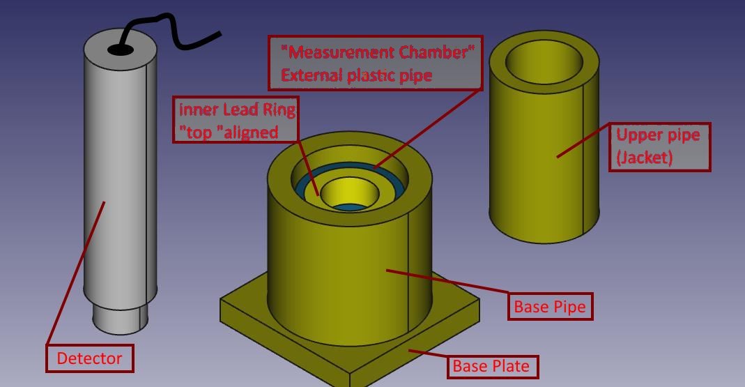
৮а•З১а•Г১а•Н৵ а§Ѓа•За§В а§Па§Х а§Еа§Ъа•На§Ыа•А ১а§∞а§є а§Ха§Њ ৮ড়а§∞а•На§Ѓа§Ња§£
৶ৌ usare misurare il Livello di Radioattivit√† а§°а•За§≤ fondo naturale а§И di sostanze debolmente radioattive ৙а•На§∞১ড়.
а§Й৙ৌৃ а§Ха•З а§Па§Х а§ђа•За§Є ৙а•На§≤а•За§Я а§Ха•З а§єа•Л১а•З а§єа•Иа§В, ৙а•На§≤а§Є а§Ха•Ба§Ы а§Чৌ৥৊ৌ а§Єа§ња§≤ড়৮а•На§°а§∞а•Ла§В, ৵ড়а§≠ড়৮а•Н৮ а§Жа§Ха§Ња§∞а•Ла§В а§Фа§∞ thicknesses а§Ха•З. а§Яа•Аа§Жа§∞а§П а§Ѓа•Иа§В componenti а§Па§Єа§Жа§И lascia а§Єа§Ва§ѓа•Ба§Ха•Н১ а§∞а§Ња§Ја•На§Яа•На§∞ ৙а•Л’ а§Ха•А а§Єа•Ба§Єа•Н১, а§Ж৶а•З৴ а§Ѓа•За§В ৵ড়৲ৌ৮৪а§≠а§Њ а§Ха•А а§Єа•Б৵ড়৲ৌ а§Ха•З а§≤а§ња§П вАЩ.
а§Єа§Ња§Ѓа§Ча•На§∞а•А ৵ৌ৪а•Н১৵ а§Ѓа•За§В ৙а•А১а§≤ а§≤а•Аа§° а§єа•И, а§Єа•З а§ѓа§є а§≠а•З৶ а§Ха§∞৮а•З а§Ха•З а§≤а§ња§П вАЩ а§Ьа§Ња§Ва§Ъ а§Ча•На§∞а•З а§Еа§≤а•На§ѓа•Ба§Ѓа•А৮ড়ৃু, а§Ьа§ђа§Ха§њ а§Жа§В১а§∞а§ња§Х а§Єа§ња§≤а•За§Ва§°а§∞ а§Ха•З а§Яа•Ба§Ха§°а§Ља•З (а§Ѓа•Б৴а•На§Ха§ња§≤ а§Єа•З ৶ড়а§Ца§Ња§И) а§Е৶а•Н৵ড়১а•Аа§ѓ а§єа•И вА٠৙а•На§≤а§Ња§Єа•На§Яа§ња§Х а§Ха•З, а§≤а•Аа§° а§Ѓа•За§В а§Чৌ৥৊ৌ а§Еа§Ва§Ча•В৆а•А а§Ха•З ৪ৌ৕.
а§Єа§≠а•А а§≤а•Аа§° а§≠а§Ња§Ча•Ла§В ৴а•Аа§Я ৲ৌ১а•Б а§Єа•З ৐৮а•З ৕а•З 1,5 а§Ѓа§ња§Ѓа•А а§Ѓа•Ла§Яа•А, а§Па§Х а§Жа§Ѓ а§ђа§ња§≤-৙১а•На§∞а§Х а§Ха•З ৪ৌ৕ а§Ха§Ња§Яа§Њ а§Фа§∞ ৺ৌ৕ а§Єа•З а§Жа§Ха§Ња§∞, а§≤৙а•За§Яа•Л а§Па§≤а•На§ѓа•Ва§Ѓа•А৮ড়ৃু/а§Єа•На§Яа•Аа§≤/৙а•На§≤а§Ња§Єа•На§Яа§ња§Х а§Ха•З а§Єа§ња§≤а•За§Ва§°а§∞а•Ла§В а§Ха•З а§Ж৪৙ৌ৪ а§Ѓа•Иа§В а§Й৙а§≤а§ђа•На§І ৕ৌ (а§Ха•З৵а§≤ а§Ха•З а§∞а•В৙ а§Ѓа•За§В а§За§Єа•Н১а•За§Ѓа§Ња§≤ а§Ха§ња§ѓа§Њ “৙а•Иа§Єа§Њ а§≠а•А”).
а§ђа•За§Є ৙а•На§≤а•За§Я а§Ха§И а§ђа§Ња§∞ ৪ুৌ৮ а§Ъа•Ма§°а§Ља§Ња§И а§Ха•А ৴а•Аа§Я ৲ৌ১а•Б а§Ха•З а§Па§Х а§Єа•На§Яа•На§∞ড়৙ ১৺ ৶а•Н৵ৌа§∞а§Њ а§Ха§ња§ѓа§Њ а§Ьৌ১ৌ а§єа•И, а§Па§Х а§Єа§≠а•На§ѓ а§Ѓа•Ла§Яа§Ња§И а§єа•Л а§∞а§єа•А.
৴а•Аа§Я а§Ж৪ৌ৮а•А а§Єа•З а§Па§Х ১ৌа§≤а§ња§Ха§Њ а§Ха•З а§Єа•Аа§Іа•З ৐৥৊১ а§Ха•З а§Ъа§Ња§∞а•Ла§В а§Уа§∞ а§Эа•Ба§Х১ৌ а§Фа§∞ ৺৕а•Ма§°а§Ља§Њ а§Ха•З ৪ৌ৕ ৮а§≤ ৪৙ৌа§Я а§Ха§∞а•З. а§≤а•Аа§° а§ђа§єа•Б১ а§єа•А ৮ড়а§В৶৮а•Аа§ѓ а§єа•И.
а§Єа§≠а•А а§Яа•Ба§Ха§°а§Ља•Ла§В ৙а§∞а•Нৃৌ৙а•Н১ а§Ъа•Ма§°а§Ља§Њ а§Ха§Ња§Ча§Ь а§Ха•З ৪ৌ৕ а§≤ড়৙а§Яа•З ৕а•З, ১а•Л а§Й৮а•На§єа•За§В ৮৺а•Аа§В а§Ж১а•А ৮а•З১а•Г১а•Н৵ а§Ха•З ৪ৌ৕ а§Єа•Аа§Іа•З а§Єа§В৙а§∞а•На§Х а§Ѓа•За§В а§єа•Иа§Ва§°а§≤, а§Ха§њ а§Е৙৮а•З ৺ৌ৕ а§Ча§В৶а•З а§єа•Л а§Ьৌ১ৌ а§єа•И. а§≠а•А а§Ха•На§ѓа•Ла§В а§Па§Х а§Ыа•Ла§Яа•З а§Ха•А а§Ча§£а§®а§Њ а§Ха§∞৮а•З а§Ха•З а§≤а§ња§П а§Еа§Ъа•На§Ыа§Њ а§єа•И’ ৵ড়а§≠ড়৮а•Н৮ diameters а§Ха•З а§Яа•Ба§Ха§°а§Ља•Ла§В а§Ха•З а§ђа•Аа§Ъ а§Ха•А а§Єа•Ба§Єа•Н১, ১а•Л а§Йа§Є а§Ха§Ња§Ча§Ь а§Ха•Ла§Яа§ња§Ва§Ч а§Єа§≠а•А а§Єа§ња§≤а•За§Ва§°а§∞а•Ла§В а§Ха•З а§Ха§ња§Єа•А а§≠а•А а§Єа§Ѓа•На§Ѓа§ња§≤৮/৮ড়ৣа•На§Ха§∞а•На§Ја§£ ১а•Ла§°а§Љ ৮৺а•Аа§В а§Ха§∞১ৌ ১а•Л вАЩ а§єа•А, а§Ха§њ а§Жа§В৴ড়а§Х а§∞а•В৙ а§Єа•З а§Па§Х а§Еа§В৶а§∞ а§Ђа§ња§Я а§Ха§∞৮ৌ а§єа•Ла§Ча§Њ вАЩ а§Еа§Іа§ња§Х (а§≤а§ња§П а§Ха•З а§∞а•В৙ а§Ѓа•За§В а§Єа§ња§≤а•За§Ва§°а§∞ а§Фа§∞ а§Яа•Й৙ ৴а§∞а•На§Я)
ুৌ৙৮а•З а§Ха•З а§≤а§ња§П а§Ж৙ а§За§Є ৙а•Иа§Яа§∞а•Н৮ а§Ха§Њ ৙ৌа§≤৮ а§Ха§∞а•За§В:
- ৙৺а§≤а•А а§ђа§Ња§∞ а§Па§Х а§Ѓа•За§Ь ৙а§∞ а§ђа•За§Є ৙а•На§≤а•За§Я а§Фа§∞ а§Ѓа•Ва§≤ а§Єа§ња§≤а•За§Ва§°а§∞ а§Й৆১ৌ а§єа•И;
- а§Ж৙ ৮ুа•В৮ৌ а§Жа§Іа§Ња§∞ а§Яа•На§ѓа•Ва§ђ а§Ѓа•За§В ৙а§∞а•Аа§Ха•На§Ја§£ а§Ха§ња§ѓа§Њ а§Ьа§Њ а§Ха§∞৮а•З а§Ха•З а§≤а§ња§П а§Єа§Ѓа•На§Ѓа§ња§≤ড়১ а§Ха§∞а•За§В, а§З১৮ৌ а§єа•И а§Ха§њ а§ѓа§є а§Еа§В৶а§∞ а§Ыа•В а§≤а•З১а•А а§єа•И (৮ড়а§Ъа§≤а•З) Dell вА٠ুৌ৙৮а•З а§Ъа•Иа§Ва§ђа§∞ а§Ха•А а§Еа§Ва§Ча•В৆а•А: а§Ж৙ а§Ха•З ১৺১ а§За§Єа•З а§Ха§∞৮а•З а§Ха•З а§≤а§ња§П а§Яа§Х а§Ха§∞ а§Єа§Х১а•З а§єа•Иа§В а§Й৙ৃа•Ба§Ха•Н১ spacers;
- а§Ж৙ а§Ха•Л ুৌ৙৮а•З а§Ъа•Иа§Ва§ђа§∞ а§°а§Ња§≤ (৙а•На§≤а§Ња§Єа•На§Яа§ња§Х а§Єа§ња§≤а•За§Ва§°а§∞ а§Фа§∞ а§Єа•Аа§Єа§Њ а§Єа§єа§Ња§ѓа§Х а§∞а§ња§Ва§Ч) ১а•Л ৮ুа•В৮ৌ ৮а•Аа§Ъа•З а§Ха•З ১а§≤ ৙а§∞ а§Ха•З৮а•Н৶а•На§∞ড়১ а§єа•И вАЩ а§Ха•А а§Еа§Ва§Ча•В৆а•А;
- ৵৺ а§Ђа§ња§Єа§≤ а§Ьৌ১ৌ а§єа•И а§Йа§Єа§Ха•А а§Ха§Ѓа•Аа§Ьа§Љ а§Єа•З а§Еа§Іа§ња§Х а§ђа•Б৮ড়ৃৌ৶а•А вАЩ а§Єа§ња§≤а•За§Ва§°а§∞ а§Ха•З а§Еа§В৶а§∞: а§ѓа§є ৙а•На§≤а§Ња§Єа•На§Яа§ња§Х ৙ৌа§З৙ а§Фа§∞ а§Чৌ৥৊ৌ а§Еа§Ва§Ча•В৆а•А а§Ха§Њ а§Єа§Ѓа§∞а•Н৕৮ а§Ха§∞а•За§Ва§Ча•З вАЩ а§Ха•З а§≤а§ња§П а§Ыа•З৶ а§Ьа§Ња§Ва§Ъ а§Ха•З ৐ৌ৶ ৙а•На§∞৵ড়ৣа•На§Яа§њ а§Ха•А а§Е৮а•Бু১ড় ৶а•За§В а§Ха§∞৮а•З а§Ха•З а§≤а§ња§П ৮а•З১а•Г১а•Н৵ а§Ха§∞а•За§Ва§Ча•З;
- а§Ж৙ а§Ьа§Ња§Ва§Ъ а§Єа§Ѓа•На§Ѓа§ња§≤ড়১ а§Ха§∞а•За§В : а§Ѓа•За§∞а•З а§Ѓа§Ња§Ѓа§≤а•З а§Ѓа•За§В а§Єа•Аа§Іа•З а§Жа§Ха§∞а•Нৣড়১ вАЩ а§≤а•Аа§° ৮а§∞а•На§Єа§∞а•А а§Ха•Л ুৌ৙৮а•З а§Ха•А а§Еа§Ва§Ча•В৆а•А.
а§Ѓа•Иа§В৮а•З а§Ха§ња§ѓа§Њ а§єа•И ৙а§∞а•Аа§Ха•На§Ја§£а•Ла§В а§Єа•З а§За§Є а§Єа•За§Яа§Е৙ а§Ха•З а§≤а§ња§П ৙а•Га§Ја•Н৆а§≠а•Ва§Ѓа§њ ৴а•Ла§∞ а§≤а§Ча§≠а§Ч а§Ха§Ѓ а§Ха§∞ ৶а•З১ৌ а§єа•И 20 а§Єа•А৙а•Аа§Па§Є а§Ха•З а§≤а§ња§П 3,1 а§Єа•А৙а•Аа§Па§Є
а§Ѓа§Ња§∞а•На§Ха•Л Russiani
а§За§Є ৙а§∞а§ња§ѓа•Ла§Ь৮ৌ а§Ха•З а§°а§Ња§Й৮а§≤а•Ла§°, а§Еа§Іа§ња§Х а§Ьৌ৮а§Ха§Ња§∞а•А а§Фа§∞ а§Ъড়১а•На§∞а•Ла§В а§Ха•З ৪ৌ৕ ৙а•Ва§∞а•На§£ а§Ха§∞а•За§В:
![]() Theremino_Pozzetto_di_Misura_ITA.pdf
Theremino_Pozzetto_di_Misura_ITA.pdf
![]() Theremino_G-Ray_Test_Chamber_ENG.pdf
Theremino_G-Ray_Test_Chamber_ENG.pdf
а§Єа§В৙а•Ва§∞а•На§£ а§Єа•Н৙ৣа•На§Яа•Аа§Ха§∞а§£ а§Ха•З а§≤а§ња§П ৲৮а•Нৃ৵ৌ৶.
а§Ѓа•Иа§В а§Ж৙а§Ха•Л а§Ха§ња§Єа•А а§≠а•А а§Ша§Я৮ৌа§Ха•На§∞а§Ѓ а§Єа•З а§Е৵а§Ч১ а§Ха§∞ৌ১ৌ а§∞а§єа•Ва§Ва§Ча§Њ
Cordially
Luca
৮ু৪а•На§Ха§Ња§∞, а§Ѓа•Иа§В а§Па§Х Theremino PMT а§Пৰৌ৙а•На§Яа§∞ V3.3 а§Ха•Л а§Ђа§ња§∞ а§Єа•З а§Єа§Ха•На§∞а§ња§ѓ а§Ха§∞৮а•З а§Ха•А а§Ха•Л৴ড়৴ а§Ха§∞ а§∞а§єа§Њ а§єа•Ва§В, а§Ьа•Л а§Ѓа•Иа§В৮а•З а§Ха•Ба§Ы а§Єа§Ња§≤ ৙৺а§≤а•З а§Ца§∞а•А৶ৌ ৕ৌ.
а§Еа§Ча§∞ а§Ѓа•Иа§В а§Е৙৮а•З а§Ха§В৙а•На§ѓа•Ва§Яа§∞ а§Ѓа•За§В а§Єа§В৴а•Л৲ড়১ USB а§Єа•На§Яа§ња§Х а§Єа§Ѓа•На§Ѓа§ња§≤ড়১ а§Ха§∞১ৌ а§єа•Ва§В ১а•Л а§ѓа§є ৮ড়а§∞а§В১а§∞ а§Па§≤а§Иа§°а•А ৶ড়а§Цৌ১ৌ а§єа•И а§Фа§∞ ৕а•Ла§°а§Ља•А ৶а•За§∞ ৐ৌ৶ а§ђа•На§≤а§ња§Ва§Х а§Ха§∞৮ৌ ৴а•Ба§∞а•В а§Ха§∞ ৶а•З১ৌ а§єа•И.
а§≤а•За§Хড়৮ а§Ѓа•Иа§В ৙а•Аа§Па§Ѓа§Яа•А а§Па§°а•Й৙а•На§Яа§∞ а§ђа•Йа§Ха•На§Є ৙а§∞ а§Ьа•Л а§Ха•Ба§Ы а§≠а•А а§Ха§∞১ৌ а§єа•Ва§В, ৵৺ а§Ѓа•Ба§Эа•З ৮৺а•Аа§В ৶ড়а§Ц১ৌ “а§Ѓа§Ња§За§Ха•На§∞а•Ла§Ђа§Ља•Л৮” а§З৮৙а•Ба§Я а§Єа•Н১а§∞. а§Ѓа•Ба§Эа•З а§ђа•Йа§Ха•На§Є а§Ѓа•За§В а§Яа•На§∞а§Ња§Ва§Єа§Ьа•За§Ва§°а§∞ а§Єа§Ња§Йа§Ва§° а§Єа•Б৮ৌа§И ৶а•З১ৌ а§єа•И. а§єа•Л а§Єа§Х১ৌ а§єа•И а§Ха§њ а§ђа•Йа§Ха•На§Є а§Єа•З а§Ьа•Ба§°а§Ља§Њ ৙а•Аа§Па§Ѓа§Яа•А а§Яа•Ва§Я а§Ча§ѓа§Њ а§єа•Л?
а§Еа§Ча§∞ а§Ѓа§Ња§За§Ха•На§∞а•Ла§Ђа•Л৮ а§З৮৙а•Ба§Я ৆а•Аа§Х а§єа•И ১а•Л а§Ѓа•Иа§В а§Ха•Иа§Єа•З а§Ьа§Ња§Ва§Ъ а§Єа§Х১ৌ а§єа•Ва§В? ৙а•Аа§Па§Ѓа§Яа•А а§Па§°а•З৙а•На§Яа§∞ а§ђа•Йа§Ха•На§Є а§Ха•Л а§єа§Яৌ৮а•З а§Фа§∞ а§ѓа•Ва§Па§Єа§ђа•А а§Фа§∞ а§ђа•Йа§Ха•На§Є а§Ха•З а§ђа•Аа§Ъ а§Х৮а•За§Ха•Н৴৮ а§Ха•За§ђа§≤ а§Ха•З а§Єа§В৙а§∞а•На§Ха•Ла§В а§Ха•Л а§Ыа•В৮а•З а§Єа•З а§Ха•Ла§И а§Ѓа§Ња§За§Ха•На§∞а•Ла§Ђа•Л৮ а§Єа§ња§Ча•Н৮а§≤ ৮৺а•Аа§В ৶ড়а§Ц১ৌ а§єа•И.
а§Ха•Г৙ৃৌ а§Ѓа•Ба§Эа•З а§Ха•Ба§Ы ু৶৶ ৶а•За§В!
а§ђа§єа•Б১ ৲৮а•Нৃ৵ৌ৶, ৙а•Йа§≤
а§Ха•Г৙ৃৌ а§Па§Х а§Єа§єа•А а§Ѓа§Ња§Йа§Є а§ђа§Я৮ а§Ха§∞а•За§В а§Фа§∞ а§Е৙৮а•А а§≠а§Ња§Ја§Њ а§Ѓа•За§В а§Е৮а•Б৵ৌ৶ а§Ха§∞а•За§В.
৶а•Ва§∞ а§Єа•З а§Єа§Ѓа§Э৮ৌ а§Ѓа•Б৴а•На§Ха§ња§≤ а§єа•И. а§Ж৙а§Ха•Л а§Па§Х а§За§≤а•За§Ха•На§Яа•На§∞а•Й৮ড়а§Ха•На§Є ৵ড়৴а•За§Ја§Ьа•На§Ю а§Ха•А а§Ж৵৴а•На§ѓа§Х১ৌ а§єа•Ла§Ча•А, а§Жа§∞а•За§Ца•Ла§В а§Фа§∞ а§Ха•Ба§Ы а§Й৙а§Ха§∞а§£а•Ла§В а§Ха•З ৪ৌ৕ а§Єа§Ѓа§Э а§Єа§Х১а•З а§єа•Иа§В а§Ха§њ а§Ха•На§ѓа§Њ а§єа•Ба§Ж.
а§Ѓа•Иа§В а§Ж৙а§Ха•Л а§Ха•Ба§Ы а§Єа§≤а§Ња§є ৶а•З৮а•З а§Ха•А а§Ха•Л৴ড়৴ а§Ха§∞১ৌ а§єа•Ва§В…
ৃ৶ড় ৵ড়а§Ва§°а•Ла§Ь а§Па§°а•З৙а•На§Яа§∞ а§З৮৙а•Ба§Я а§Ха•Л ৶а•За§Ц১ৌ а§єа•И а§Ьа•Л а§Па§°а•З৙а•На§Яа§∞ а§Х৮а•За§Ха•На§Я а§Ха§∞১а•З а§Єа§Ѓа§ѓ а§Ьа•Ла§°а§Ља§Њ а§Ьৌ১ৌ а§єа•И ১а•Л а§Ха§Ѓ а§Єа•З а§Ха§Ѓ а§ѓа•Ва§Па§Єа§ђа•А ৙ৌа§∞а•На§Я а§Ха§Ња§Ѓ а§Ха§∞১ৌ а§єа•И.
а§Ьа§ђ а§Ж৙ а§Па§°а•Й৙а•На§Яа§∞ а§Ха•Л USB а§Ѓа•За§В ৙а•На§≤а§Ч а§Ха§∞১а•З а§єа•Иа§В ১а•Л ৵ড়а§Ва§°а•Ла§Ь а§Єа§єа•А а§Ж৵ৌа§Ь а§Ха§∞১ৌ а§єа•И?
৴ৌৃ৶ а§Ьа•Иа§Х ৙а•Ва§∞а•А ১а§∞а§є а§Єа•З а§°а§Ња§≤а§Њ ৮৺а•Аа§В а§Ча§ѓа§Њ а§єа•И?
а§єа•Л а§Єа§Х১ৌ а§єа•И а§Ха§њ а§Ђа•Ла§Яа•Ла§Ѓа§≤а•На§Яа•А৙а•На§≤а§Ња§ѓа§∞ а§Ха•Л а§Ха•Ба§Ы а§єа•Ба§Ж а§єа•Л?
৴ৌৃ৶ а§Й৪৮а•З а§Па§Х а§єа§ња§Я а§≤а§ња§ѓа§Њ а§Фа§∞ а§Ча•На§≤а§Ња§Є ১а•Ла§°а§Љ ৶ড়ৃৌ?
ৃ৶ড় а§Ж৙ ৵ৌ৪а•Н১৵ а§Ѓа•За§В ৮৺а•Аа§В а§Ха§∞ а§Єа§Х১а•З а§єа•Иа§В, ১а•Л а§Ж৙а§Ха•Л а§За§Єа•З а§єа§Ѓ а§Ѓа•За§В а§Єа•З а§Па§Х а§Ха•Л ৵ৌ৙৪ а§≠а•За§Ь৮ৌ а§єа•Ла§Ча§Њ а§Фа§∞ а§єа§Ѓ а§За§Єа•З а§Ж৙а§Ха•З а§≤а§ња§П а§Ѓа•Ба§Ђа•Н১ а§Ѓа•За§В ১ৃ а§Ха§∞а•За§Ва§Ча•З (৐৴а§∞а•Н১а•З ৵ৌ৙৪ а§Ца§∞а•А৶৮а•З а§Ха•З а§≤а§ња§П а§Ха•Ла§И а§Ѓа§єа§Ва§Ча§Њ а§Ша§Яа§Х ৮ а§єа•Л)
৮ু৪а•Н১а•З Livio,
১а•Ба§∞а§В১ а§Ь৵ৌ৐ а§Ха•З а§≤а§ња§П ৲৮а•Нৃ৵ৌ৶. ৵ড়а§≠ড়৮а•Н৮ ৙а•Аа§Па§Ѓа§Яа•А а§Ьа§Ња§Ва§Ъ а§Ха•А а§Ьа§Ња§Ба§Ъ а§Єа•З а§Ѓа•Ба§Эа•З ৙১ৌ а§Ъа§≤а§Њ а§Ха§њ а§Єа§Ѓа§Єа•На§ѓа§Њ ৙а•Аа§Па§Ѓа§Яа•А а§Па§°а•Й৙а•На§Яа§∞ а§Ха•З ৪ৌ৕ ৮৺а•Аа§В а§ђа§≤а•На§Ха§њ ৙а•Аа§Па§Ѓа§Яа•А а§Ьа§Ња§Ва§Ъ а§Ѓа•За§В а§Єа•З а§Па§Х а§Ха•З ৪ৌ৕ а§єа•И. а§За§Єа§≤а§ња§П USB а§Па§°а•Й৙а•На§Яа§∞ а§Ха•А ১а§∞а§Ђ а§Єа•З а§Єа§ђ а§Ха•Ба§Ы ৆а•Аа§Х а§єа•Л৮ৌ а§Ъа§Ња§єа§ња§П.
৪ৌ৶а§∞ а§Еа§≠ড়৵ৌ৶৮, ৙а•Йа§≤
৮ু৪а•Н১а•З,
а§Ж৙а§Ха§Њ “৮а•Ба§Х৪ৌ৮ а§≠а§∞৙ৌа§И” а§Єа•Б৵ড়৲ৌ а§Ча§Ња§Ѓа§Њ а§Єа•Н৙а•За§Ха•На§Яа•На§∞а§Њ а§Ѓа•За§В а§Єа•Ба§Іа§Ња§∞ а§Ха§∞৮а•З а§Ха§Њ а§Па§Х а§Й১а•На§Ха•Га§Ја•На§Я а§Ха§Ња§Ѓ а§Ха§∞১а•А ৙а•На§∞১а•А১ а§єа•Л১а•А а§єа•И. а§Ха•На§ѓа§Њ а§Ж৙ а§Ѓа•Ба§Эа•З а§За§Є ৐ৌ১ а§Ха§Њ ৵ড়৵а§∞а§£ ৶а•З а§Єа§Х১а•З а§єа•Иа§В а§Ха§њ а§ѓа§є ৵ৌ৪а•Н১৵ а§Ѓа•За§В а§Ха•На§ѓа§Њ а§Ха§∞ а§∞а§єа§Њ а§єа•И??
а§Ѓа•За§В https://www.theremino.com/en/downloads/radioactivity v4.2 а§Ха•З ৵ড়৵а§∞а§£ а§Ѓа•За§В а§За§Єа•З "а§∞а§ња§Ьа§Ља•Йа§≤а•На§ѓа•В৴৮ а§Ѓа•Ба§Ж৵а§Ьа§Њ" а§Ха§єа§Њ а§Ьৌ১ৌ а§єа•И. а§Ѓа•За§В https://www.theremino.com/wp-content/uploads/files/GammaSpec_ENG.pdf ৙а•Аа§Ьа•А . ৙а§∞ 35 а§ѓа§є а§Ха§єа§Њ а§Ьৌ১ৌ а§єа•И “৵а•Нৃৌ৙а§Х а§Ѓа•Ба§Ж৵а§Ьа§Њ”. а§Ѓа•За§В https://physicsopenlab.org/2016/02/07/energy-resolution-in-gamma-spectrometry/ а§ѓа§є а§Ха§єа§Њ а§Ьৌ১ৌ а§єа•И “а§Єа•Йа§Ђа•На§Я৵а•За§ѓа§∞ а§Ѓа•Ба§Ж৵а§Ьа§Њ”.
а§Ха•На§ѓа§Њ а§ѓа•З ৵৺а•А ৐ৌ১ а§єа•Иа§В? а§ѓа§є ৵ৌ৪а•Н১৵ а§Ѓа•За§В а§Ха•На§ѓа§Њ а§Ха§∞ а§∞а§єа§Њ а§єа•И?
৲৮а•Нৃ৵ৌ৶!
а§єа§Ња§Б ৵а•З ৵৺а•А а§єа•Иа§В.
а§≤а•За§Хড়৮ а§Па§Ѓа§Єа•Аа§П а§Ж৵а•З৶৮ а§Ѓа•За§В а§Па§Х ৶а•Ва§Єа§∞а•А ৵ড়৲ড় а§≠а•А ৴ৌুড়а§≤ а§єа•И а§Ьа§ња§Єа•З а§Ха§єа§Њ а§Ьৌ১ৌ а§єа•И “৵ড়а§Ша§Я৮”.
а§Ж৙ а§єа§Ѓа§Ња§∞а§Њ а§Па§Ѓа§Єа•Аа§П а§Р৙ а§°а§Ња§Й৮а§≤а•Ла§° а§Ха§∞ а§Єа§Х১а•З а§єа•Иа§В. а§Фа§∞ ৮ড়ুа•Н৮а§≤а§ња§Цড়১ ৙а•Га§Ја•Н৆а•Ла§В а§Єа•З а§Єа§≠а•А ৶৪а•Н১ৌ৵а•За§Ьа§Ља•Аа§Ха§∞а§£ а§Ђа§Ља§Ња§За§≤а•За§В:
https://www.theremino.com/en/downloads/radioactivity
https://www.theremino.com/en/technical/schematics#pmtadapter
https://www.theremino.com/en/blog/gamma-spectrometry
৮ড়ুа•Н৮а§≤а§ња§Цড়১ а§Єа•Аа§Іа•З а§≤а§ња§Ва§Х а§Ѓа•За§В а§Ж৙а§Ха•Л а§Е৙৮а•З ৙а•На§∞৴а•Н৮а•Ла§В а§Ха•З а§ђа§Ња§∞а•З а§Ѓа•За§В а§Еа§Іа§ња§Х ৶ড়а§≤а§Ъа§Єа•Н৙ а§Ђа§Ља§Ња§За§≤ а§Ѓа§ња§≤а•За§Ча•А:
https://www.theremino.com/wp-content/uploads/files/ThereminoMCA_Deconvolution_ENG.pdf
https://www.theremino.com/wp-content/uploads/2012/11/MinimizingFWHM_ITA_ENG_PDF.zip
https://www.theremino.com/wp-content/uploads/2012/11/ThereminoMCA_Documentation_ENG_JAP.zip
https://www.theremino.com/wp-content/uploads/files/GammaSpec_ENG.pdf
а§Ха•Ба§Ы а§Єа§Яа•Аа§Х…
৮ড়ুа•Н৮ а§Ха•З а§Еа§≤ৌ৵ৌ “а§Єа§Ва§Ха§≤а•Н৙ а§Ѓа•Ба§Ж৵а§Ьа§Њ” а§єа§Ѓа§Ња§∞а•З а§Па§Ѓа§Єа•Аа§П а§Ж৵а•З৶৮ а§Ѓа•За§В а§Па§Х а§єа•И “а§Ча§Ња§Ка§Єа•А deconvolution”.
৶а•Л ৵ড়৲ড়ৃа•Ла§В а§Ха•З ৮ড়ৃа§В১а•На§∞а§£ а§Яа•Иа§ђ а§Ѓа•За§В ৶а•Л а§Еа§≤а§Ч-а§Еа§≤а§Ч ৙а•И৮а§≤а•Ла§В а§Ѓа•За§В а§єа•Иа§В “৵ড়а§Ха§≤а•Н৙” а§Па§Ѓа§Єа•Аа§П а§Ж৵а•З৶৮ а§Ха•З.
– а§Ха•Л “а§Єа§Ва§Ха§≤а•Н৙ а§Ѓа•Ба§Ж৵а§Ьа§Њ” а§Па§Х а§Єа§∞а§≤ ৴ৌа§∞а•Н৙৮ড়а§Ва§Ч а§Па§≤а•На§Ча•Ла§∞ড়৕ু а§єа•И, а§Ы৵ড় а§Єа§В৙ৌ৶а§Ха•Ла§В а§Ха•З ৪ুৌ৮ а§Ха§Ња§∞а•На§ѓа•Ла§В а§Ха•Л ১а•За§Ь а§Ха§∞৮ৌ. ৴ৌа§∞а•Н৙৮ড়а§Ва§Ч а§Ха•Л а§Па§Х а§Єа•Иа§В৙а§≤ а§Фа§∞ а§Па§°а§ња§Па§Єа•За§Ва§Я а§Єа•Иа§В৙а§≤ а§Ха•З а§Еа§В১а§∞ а§Ѓа•За§В ৵а•Г৶а•На§Іа§њ а§Ха•З ৪ৌ৕ а§≤а§Ња§Ча•В а§Ха§ња§ѓа§Њ а§Ьৌ১ৌ а§єа•И. а§Ж৙ а§За§Єа•З а§Па§Х ৵а•На§ѓа•Б১а•Н৙৮а•Н৮ а§Ха§Ња§∞а•На§ѓ а§Ха•З а§∞а•В৙ а§Ѓа•За§В а§≠а•А а§Єа•Ла§Ъ а§Єа§Х১а•З а§єа•Иа§В. а§Й৙ৃа•Ла§Ч а§Ха§ња§П а§Ча§П а§Па§≤а•На§Ча•Ла§∞ড়৶ু а§Ха•Л а§Ђа§Ља§Ња§За§≤ а§Ѓа•За§В а§Єа§Ѓа§Эа§Ња§ѓа§Њ а§Ча§ѓа§Њ а§єа•И “Minimizingfwhm”, ৙৮а•Н৮а•Ла§В а§Ѓа•За§В 22 а§Ха§∞৮а•З а§Ха•З а§≤а§ња§П 25. а§єа§Ѓа§Ња§∞а§Њ а§Ха§Ња§∞а•Нৃৌ৮а•Н৵ৃ৮ а§Па§Ѓа§Єа•Аа§П а§Ж৵а•З৶৮ а§Єа•На§∞а•Л১а•Ла§В а§Ѓа•За§В а§єа•И, а§Ђа§Ља§Ња§За§≤ а§Ѓа•За§В “а§Ха•На§≤а§Ња§Є_а§Єа•Н৙а•За§Ха•На§Яа•На§∞а•Ла§Ѓа•Аа§Яа§∞”, а§Єа§Ѓа§Ња§∞а•Ла§є а§Ѓа•За§В “а§Ђа§ња§≤а•На§Яа§∞ а§≤а§Ња§Ча•В а§Ха§∞а•За§В”.
– а§Ха•Л “а§Ча§Ња§Ка§Єа•А deconvolution” а§Ђа§Ља§Ња§За§≤ а§Ѓа•За§В а§Еа§Ъа•На§Ыа•А ১а§∞а§є а§Єа•З а§Єа§Ѓа§Эа§Ња§ѓа§Њ а§Ча§ѓа§Њ а§єа•И “ThereminoMCA_Deconvolution”.
৵ড়৪а•Н১а•Г১ а§Й১а•Н১а§∞ а§Ха•З а§≤а§ња§П а§ђа§єа•Б১-а§ђа§єа•Б১ ৲৮а•Нৃ৵ৌ৶. а§Ѓа•Ба§Эа•З а§Ча§Ња§Ка§Єа•А а§°а§ња§Ха•Й৮а•Н৵а•Ла§≤а•На§ѓа•В৴৮ ৙а§∞ ৮а•Ла§Я а§Ѓа§ња§≤а§Њ ৕ৌ. а§Ѓа•Иа§В а§Е৮а•На§ѓ а§°а•Йа§Ха•На§Є а§Ха§Њ а§Еа§Іа•Нৃৃ৮ а§Ха§∞а•Ва§Ва§Ча§Њ.
৮ু৪а•На§Ха§Ња§∞,
I am trying to modify the 3D sound card adapter, а§єа§Ња§≤а§Ња§Ва§Ха§њ, they don’t make them exactly like the one in the instructions. Does anyone have the updated instructions on how to modify the audio sound card (perhaps some schematics as well).
৲৮а•Нৃ৵ৌ৶!
а§ѓа•Ва§Ьа•А৮
If the sound card is different no one can help without reverse engineering your card.
My best advice is to follow the MIC signal all the way to the chip and then figure out where to cut and where to put the components.
I’m sorry but only you (or some of your friends who are experts in electronics) can do it.
৮ু৪а•Н১а•З Livio, a have a theremino master DIL-V5.
How can I make the Theremino MCA recongnise the signals from USB port of my computer ?
The Theremino MCA only recongnise sinals of the microphone.
Or how can I do to get a analogic sinal on pin 1 and transmit a digital sinal from pin 2.
The Theremino-MCA application only recongnize the microphone signals.
If you do not have the modified sound card, you could use any sound-card with a MIC input, also without modifications.
The noise at the low energies will be more than normal but it will work.
How can I do to receave an analogic signal on the Theremino Master DIL-V5 and transmit to the sound card with a MIC imput ?
thanks for answering me
The Master can not receive audio signals.
You can not use the master for the Gamma Spectrometry.
You MUST use a NaiTl Christal and a PMT tube and then connected the PMT to a PMT-Adapter and then connect the PMT-Adapter output to an audio card MIC input.
A better alternative is to use a PMT_AudioAdapter directly connected to the USB
Call to Lello if you can not build these components.
Lello = ufficiotecnico@spray3d.it
Lello seller on eBay = maxtheremino
৮ু৪а•Н১а•З Livio,
I am working on making a portable version of Gamma spectrometer. Where can I get an MCA system for Apple (iPhone and iPad)? The one listed on Apple store is just a Geiger counter (Geiger а§ђа•Аа§Уа§Яа•А) and doesn’t have a spectrometry function.
৲৮а•Нৃ৵ৌ৶,
а§ѓа•Ва§Ьа•А৮
а§Ха•На§Ја§Ѓа§Њ а§Ха§∞а•За§В, we know windows systems only and so we can not help about this.
To make working our projects on systems other than Windows is very difficult and requires a deep knowledge about programming those systems.
Livio,
I am talking about the same system by Theremino you guys mentioned on the same webpage where we are right now. Just scroll up a few:
“By popular demand Alessio has designed a special version of PmtAdapter, usable with software available on iPhone and iPad. The software is called Geiger bot, ed √® un riferimento per la comunit√† Apple.”
а§Ха•На§Ја§Ѓа§Њ а§Ха§∞а•За§В, I was thinking about our MCA software, but if you need the hardware only maybe it is possible.
Now I explore this old project (а§Ха•З а§ђа§Ња§∞а•З а§Ѓа•За§В 5 а§ѓа§Њ 10 а§Єа§Ња§≤а•Ла§В ৙৺а§≤а•З) and then I write another message explaining how to obtain this hardware module or build it (if possible).
I looked at Alessio’s section. Now a small tablet with Windows would cost even less than 100 Euros and the resulting spectrums would be significantly better.
But if you really want to do it with Apple you will need:
1) The Geiger Bot app : https://apps.apple.com/it/app/geiger-bot/id427728355
2) A PMT Adapter that you can build yourself or have it built by Lello as explained here:
https://www.theremino.com/en/blog/gamma-spectrometry
3) Power the PMT Adapter with a 5 volt you can find it everywhere but be careful that it must not be noisy. A power bank would do very well while a 220V power adapter would not do.
4) Add a resistive divider or a trimmer to the PMT Adapter output.
5) Connect the PMT Adapter output to a Jack suitable to the Apple input (probably it will take a 4-pole jack and the signal should be the tip)
If you have Lello do it, I’ll explain to him how to divide and which Jack to use. But in this case you will also have to tell exactly which Apple you have to connect it to and if possible tell us how the Jack for the microphone input must be made.
To contact Lello write your mail in the message data (we will not publish it),
or write to Lello at: ufficiotecnico@spray3d.it
Ok thank you!
а§ѓа•Ва§Ьа•А৮
৮ু৪а•Н১а•З Livio,
I’ve been using the MCA for a good while now for XRF above 10 а§Ха•А৵, the lowest possible with my sensor NaI PMT set up, and with good results. Thank you for providing this application.
а§єа§Ња§≤а§Ња§Ва§Ха§њ, for the energy ranges below that I plan to use a X100-7 diode sensor for which I have a Micod amplifier and shaper board as described by Lodovico in the article ‘Si-PIN Photodiode with Micod CSA-SA’. He mentions in the article that the pulse width of the output is 15 uS and not very compatible with the MCA. Is there a way to improve the the MCA’s response to the signal perhaps by tweaking settings?
а§≠а•А, I have not been successful in adding adding new entries to the Isotope list. How does that work?
৪ৌ৶а§∞
а§Ж৶ড়
Hi ECC
I advise against photodiodes, we have never managed to make them go well, too noisy (compared to the right PMT and in the best working conditions as we have indicated). However you can experiment with the application controls (especially the Baseline test and Params panels) and if you can’t get it right we won’t know what to do or what to change.
The Edit Sample Rows File button is only used to select some commonly used isotopes, you can add or remove some. But it is only used to select the square boxes.
The long table is stored at the end of the INI file next to the application executable. You can edit the isotopes and also add new ones as explained on page 5 ৮ড়а§∞а•Н৶а•З৴а•Ла§В а§Ха§Њ.
HI
Livio
а§єа§Ња§ѓ Livio,
Thanks for your advice concerning photo diodes, I hear you there. Seeing that I have all the parts already – including some Am241 buttons – and can’t afford buying a another better, low energy PMT just for XRF below the 10 keV range – I may give it a try anyway.
What I did already plan for improving the diode noise situation – other than using batteries as power supplies – is cooling the detector diode’s small mounting board (amplifier board as well?) with a Peltier element.
Starting with an existing fan cooled set up which can pull down a leaky and uninsulated small box to -7 C should provide some initial data.
If a measurement chamber was evacuated to say 500 mBar – what would be the effects? Would that help to increase the energy reaching the sample from the Am241 buttons and in turn the detector?
As for the Am241 buttons illuminating the sample – what would their most effective and practical angle and distance relative to the detector?
Following instructions I successfully added an Isotope. ৲৮а•Нৃ৵ৌ৶.
৪ৌ৶а§∞
а§Ж৶ড়
The isotope list is at the end of the “а§Еа§≠а•А а§°а§Ња§Й৮а§≤а•Ла§° а§Ха§ња§ѓа§Њ а§Ча§ѓа§Њ Theremino MCA v” а§Ђа§Ља§Ња§За§≤. You could edit this file also with Notepad (when the MCA app is not running).
You could also find in the folder “а§Е১ড়а§∞а§ња§Ха•Н১” the following lists and other useful files:
– Isotopes_Energy.txt
– Isotopes_Energy-with-medicals.txt
– LibraryNaI.txt
– XRFTable.txt
৲৮а•Нৃ৵ৌ৶ Livio. I will check that out
৮ু৪а•На§Ха§Ња§∞, I have a few questions about the MCA help documentation:
1. The document says that the preamplifier amplifies the original pulse by 30dB to the ADC. The data sheet for the CM108AH sound card shows an ADC range of 2.88Vpp. Data from other sources show that the original pulse amplitude of PMT is already higher than 1V. Does it still need to be amplified by another 30dB? (up to 1000X)
2. The data sheet of the CM108AH sound card shows that the maximum ADC sampling rate is 48K/44.1KHz. How does the MCA document claim 192KHz?
1) I don’t know what the “other sources” are referring to when they say 1 ৵а•Ла§≤а•На§Я.
The pulse coming from the PMT tube is a current, not a voltage of 1 ৵а•Ла§≤а•На§Я, and our circuit amplifies it just enough but not too much so that it doesn’t exceed 2.88Vpp and therefore saturate.
If our circuit is built well it does exactly what it needs.
If you want more details you should simulate with Spice and measure what happens at each point of the circuit. Or make it and measure.
2 The document says “Adjust the “Sampling” (sampling frequency of the sound card) with the highest possible value which is
usually 192000.”
а§Фа§∞ “usually 19200” does not mean that all sound cards support that value.
The Theremino MCA application can work with many different sound cards and some (very rare expensive and completely useless in our case) could even support 192 KHz native.
The CM108AH chip reaches “а§Ха•З৵а§≤” 48 KHz, which for MCA measurements is fine. Now I don’t know if it also produces the 192 KHz interpolated, you should try. If it does, choose it but in any case between 48 KHz and 192 KHz you will not see any difference in the results.
а§Ж৙а§Ха•З а§Ь৵ৌ৐ а§Ха•З а§≤а§ња§П ৲৮а•Нৃ৵ৌ৶, Livio.
My other sources refer to the fact that I have an old PMT detector, preamplifier, and single channel analyzer. According to the instruction, the preamplifier gain is set to 1X and works as a White cathode follower, and the threshold of the single-channel analyzer is adjusted to 1V. I will try to feed the signal from the White follower into the Theremino PmtAdapter.
Another major difference of my old circuit is that the PMT divider resistors are smaller, all 1M ohms. The PMT load resistance is 51K ohms.
“…I will try to feed the signal from the white cathode follower into the Theremino PmtAdapter…”
৆а•Аа§Х а§єа•И, this could work, but you need to eliminate all our signal amplifiers and go with your one volt signal directly to the input of the sound card.
“…the PMT divider resistors are smaller, all 1M ohm. The PMT load resistor is 51K ohm….”
Our power supply is not able to give that much current.
So you will have to use a different power supply.
My advice is to use our complete project and with a PMT with resistors as recommended by us.
Or not to use any part of our project and simply enter your signals into a sound card.
৮ু৪а•На§Ха§Ња§∞, I have a question about the shielding of the circuit, I understand that the box should be a metalic box, my question is, the box should be conected to the ground of the circuit, right ?
This means that the conetor to the PMT should be electric isolated from the box, right ?
а§єа§Ња§Б,
the PMT Hi voltage connector should be electrically isolated from the metallic box
and the box should be connected to the GND (power supply negative).
In alternative you should use a plastic box and adhesive copper tape (you can find it on eBay) connected to GND to shield the output amplifier area.
To see how many shield is necessary you can see the output audio signal with our DAA scope and add and move a little shield made with PCB e nd connected with a wire to gnd.
Normally some cm3 of shield in the base (the lower part of the box) can be enough also if there are strong electric noises in the ambient. Try also with a near smarthphone when calling and speaking that is the strongest noise possible.
Circuit build, but i’m not getting any usefull signal.
Is anyone using FEU-35 photomultiplier ?
ৃ৶ড় а§Ра§Єа§Њ, what’s de circuit for the voltage divider, I’m using 10 Mohm resistors, pin1 to negative, ৙ড়৮ 10 positive, ৙ড়৮ 9 4,7 nF to pin1 negative.
I’m using a very small GSO crystal (4mm x 6mm x 20mm).
Any coments, sugestions ?
Do you have some radioactivity source (Cesium or Americium) ?
If not it is impossible to test the PMT and see if signals (with the DAA scope) are OK
Have you tested HI voltage with a high impedance tester (as explained in our site) ?
The PMT adapter sends the correct voltages to the tube, а§Ха•З а§ђа§Ња§∞а•З а§Ѓа•За§В 500 to more than 1000 ৵а•Ла§≤а•На§Я ? (৪ৌুৌ৮а•На§ѓ а§∞а•В৙ а§Єа•З а§Ха•З а§ђа§Ња§∞а•З а§Ѓа•За§В 700)
I have a lot of radioactive sources, uranium ore, thorium ore, americium, uranium glass.
Voltage is ok, I already build a lot of Geiger counters over the years, I’m use to test high impedance power sources, my real problem here is the PMT circuit, and the scintillator crystal that I’m using, maybe it’s to small…
Probably the PMT adapter is ok, а§≤а•За§Хড়৮:
1) Test the voltage on the PMT tube electrodes (maybe connectors or cable are not ok ?)
2) Test the PMT_Adapter amplifier and the Audio_Adapter chain.
To test amplifier and audio chain you could:
– Open the BNC the goes to the PMT tube (no PMT at all for this test)
– Connect the PMT output with a resistor to ground (а§єа•Л а§Єа§Х১ৌ а§єа•И 100 а§Ѓа•За§Ча§Њ а§Уа§Ѓ)
– Test the audio pulses with our DAA app they should appear each time you disconnect and connect the resistor.
is there a reason for americium 59 keV to show up in a higher value of energy?
even with the slider all the way it does not reach the corret value.
Another question, my usb audio adapter only works at 48 kHz max, what model you guys use for higher sampling frequency ?
.
If the Cesium is correct at 661 KeV then the Americium should be near to 59 +/-10 а§Ха•А৵
Photomultipliers are not perfectly linear and you should linearize the scale using the “Energy linearizer” а§Ѓа•Ба§Эа•З ৮а•Ла§Яа•На§Є а§Ъа§≤ৌ৮а•З а§Ха•З а§≤а§ња§П Theremino а§єа§Ња§∞а•Нৰ৵а•За§ѓа§∞ а§Єа§ња§Ча•Н৮а§≤ ৮৺а•Аа§В а§Ѓа§ња§≤ а§∞а§єа§Њ а§єа•И.
If the linearity errors are very large then there is something wrong in the photomultiplier resistors chain or in the calibration samples and trimming or something other…
Using a 48 kHz adapter is OK, some expensive adapter exists, but you not see any difference in the collected data.
৮ু৪а•На§Ха§Ња§∞, per quanto riguarda i vostri esperimenti con i diodi bpw34, vorrei cortesemente sapere:
Avete usato uno scintillatore con guida di luce o un accoppiamento diretto sorgente-rivelatore.
৲৮а•Нৃ৵ৌ৶, Massimiliano.
Gli esperimenti con i diodi non hanno mai dato buoni risultati.
Gli unici metodi buoni che abbiamo trovato sono i tubi Geiger e i fotomoltiplicatori con cristalli NaiTl.
Comunque no, non abbiamo usato uno scintillatore e una guida di luce.
Se guardi nel datasheet di questi diodi, la curva di risposta in funzione della lunghezza d’onda √® piccata nei 900 а§П৮а§Па§Ѓ (infrarosso), mentre l’energia delle particelle E=hc/lambda corrisponde a lunghezze d’onda piccolissime. Servirebbero, a mio modesto parere, diodi che rispondono all’ultravioletto, accoppiati a scintillatori e guide di luce; i cristalli NaITl sono scintillatori inorganici specifici per la spettrometria, ma si potrebbe tentare anche con un normale scintillatore plastico per uso generico. Il problema dei diodi UV (SIPM) √® che sono molto costosi per un hobbista, per questo ero curioso di sapere se avevate alternative pi√є economiche. ৲৮а•Нৃ৵ৌ৶, ৮ু৪а•На§Ха§Ња§∞.
Le prove con diodi le abbiamo fatte senza scintillatori, solo con diodi che ricevono direttamente i prodotti delle disintegrazioni nelle giunzioni. Pertanto non c’era bisogno di diodi sensibili a lunghezze d’onda particolari. Ma essendo la giunzione piccola il volume di cattura √® limitato e la sensibilit√† in CPS/mr/h √® molto bassa.
I SIPM sono sicuramente pi√є sensibili ma non li seguiamo pi√є perch√© hanno un rumore di fondo esagerato rispetto agli scintillatori con fotomoltiplicatore e cristallo NaiTl.
Mentre nel caso di voler fare conteggi (e non spettrometria gamma) allora non c’√® di meglio che usare tubi Geiger.
Abbiamo pubblicato due file gentilmente concessi da Physics Open Lab
https://physicsopenlab.org/
I file sono in questa pagina:
https://www.theremino.com/downloads/radioactivity
Potete scaricarli direttamente da qui con questi due link
вАУ In italiano: https://www.theremino.com/wp-content/uploads/files/GammaSpec_ITA.pdf
вАУ In inglese: https://www.theremino.com/wp-content/uploads/files/GammaSpec_ENG.pdf
What’s de maximum cps value for reliable readings ?
What’s de dead time of the system ?
I think something similar to:
1) а§Ха•З а§ђа§Ња§∞а•З а§Ѓа•За§В 10000 ৶ৌа§≤а•За§В.
2) а§Ха•З а§ђа§Ња§∞а•З а§Ѓа•За§В 100 а§єа§Ѓа•За§В
But it is impossible summarize with single numbers, read the document “SignalConditioning_ENG.pdf”
а§єа§Ња§≤а§Ња§Ва§Ха§њ, if you are going towards similar levels, rather than measuring, it is better to run away as quickly as possible.
Today, I made some tests.
I use the same methode that is used for determination of dead time in geiger counters.
I used 2 americium sources, time 300s.
at the peak of the spectrum:
source 1 = 668 samples -> 2,23 а§Єа•А৙а•Аа§Па§Є
source 1 + 2 = 1209 samples -> 4.03 а§Єа•А৙а•Аа§Па§Є
source 2 = 658 samples -> 2,19 а§Єа•А৙а•Аа§Па§Є
with this data, dead time is 0,04 s = 40 а§Па§Ѓа§Па§Є
Where is the error of this procedure ?
Dear Paulo, I’m Antonio and in the last time I’ve worked with Livio on some Cosmic Ray Project, Livio asked me to try to solve your problem with gamma spectrometry.
May You explaine me better:
а§Ѓа•За§В) what’s you have done (setup, PMT type, scintillator type , sorces type)
а§ђа•А) your calculation of dead time startin g with two separate count
৲৮а•Нৃ৵ৌ৶
Hi Antonio,
for this experiment I used feu35 + NaI (18x30mm) + americium sources
My understanding of dead time is the ability for the system to identify two individual pulses.
just using theory, we can remember Nyquist and with the sampling rate of a USB audio card, you have a limit for the maximum frequency, but that limit cannot be reached because theremino software needs to have a base line, and a pulse, all that is time, for this reason the minimum gap between pulses is lower tham the nyquist theory.
In the signal conditional pdf, we can red that in case of a pulse to close to one another the software discards the second one.
Let me just make a small remark, nothing of this gets in the way of getting a correct spectrum graph.
But nevertheless, I decided to get the dead time by experimental procedure.
And that is a simple experiment, I used two americium sources, the goal is, i use source one and take the number of samples deteted in the peak energy 59,5 а§Ха•А৵, them without moving the first source I added a second source, again I take de number of samples deteted in the peak energy 59,5 а§Ха•А৵, them I take the first source out and I take de number of samples deteted in the peak energy 59,5 а§Ха•А৵.
Wiht this experiment and if the dead time was zero, the sum of source one plus source two would be equal to the number of samples when both are present, in the numbers that I posted earlier we can see that the value is not equal:
I used 2 americium sources, time 300s.
at the peak of the spectrum:
source 1 = 668 samples -> 2,23 а§Єа•А৙а•Аа§Па§Є
source 1 + 2 = 1209 samples -> 4.03 а§Єа•А৙а•Аа§Па§Є
source 2 = 658 samples -> 2,19 а§Єа•А৙а•Аа§Па§Є
with zero dead time the value sorce 1+2 should be 668 (source 1) + 658 (source 2) = 1326
but I got 1209 insted.
With this experimental values is possible to determine dead time, I got 0,04s.
you can chek the formulas in many sites, but as an example:
https://www.umw.edu.pl/sites/default/files/2022-05/Practical%20No%2021%20Determination%20of%20the%20dead%20time%20of%20Geiger-Muller%20counter%20by%20the%20two-source%20method.pdf
Hi Paulo,
I think there are something wrong:
1) if You want to measure the sum of two sources your detector area must be much greather than the sources area, and seem me this is not possible with your scintillator area.
also seem that your sources activity is very poor, so You have not a sufficient “sample” to have a correct statistical computing.
2) You compute 0.04 sec dead time, this means 1/0.04 possible count per second that result in 25 а§Єа•А৙а•Аа§Па§Є. а§єа•А, I have used my MCA system with 50 mm diameter scintillator with a simple Th sources and I’ve read more that 400 а§Єа•А৙а•Аа§Па§Є… 16 times your result.
So my suggestions are:
-check all the measurement chain
-check the “pulse shape” visualizer: if the pulses are larger more than 100-150 us this means that there are something wrong in the circuit
-use more measurement (а§Ха§Ѓ а§Єа•З а§Ха§Ѓ 3) with half an hour time (1800 secs) for each single ( а§Ѓа•За§В,а§ђа•А, A+B) measurement , and compute the average and the standard deviation, if standar deviation is grather than 5% , increase the test time.
৴а•Ба§≠а§Хৌু৮ৌа§Па§Б.
৙а•Б৮৴а•На§Ъ: sorry wich type of MCA electronic You use?
৮ু৪а•Н১а•З, first of all I want to thank you for you time, but I have to ask you to please read my posts carefully, because probably it’s me that did not explain very weel but your remarks about my “samples” or my setup shows that you did not get what I was trying to explain.
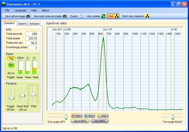
It would be simpler if I could post pictures, but I will use the picture of a cesium 137 spectrum on the top of this page. Please try to folow my next lines looking at that picture.
In the picture we can see:
Total seconds = 242
Total pulses = 181734
Pulses per sec = 725,5 this is the same as cps
now look at the line below the spectrum Energy=662,8 keV Samples=1324
with this numbers you have a full spectrum that as 725,5 cps but at the energy of 662,8 keV we have 1324 samples divided by 242 seconds = 5,47 а§Єа•А৙а•Аа§Па§Є
now, with this in mind, please read my previous post.
all that I wrote was just for the energy 59,5 а§Ха•А৵. that does not mean that the pulses per second that I have in total are low or that I have any problem in my setup or my electronics.
When I test the system with two sources I can get the dead time.
With this example of cesium imagine that you put another cesium source next to the one that get that spectrum, you will get a bigger number of counts for that energy (663,8 а§Ха•А৵) but you can use those values to get to the dead time of the system.
Dear Paulo
i am Livio of theremino system.
Pulses per sec = 725,5 means that with our hardware the dead time is less than 1.4 Ms (а§Ха•З а§ђа§Ња§∞а•З а§Ѓа•За§В 30 times less than your measured 40 Ms)
৶а•Ва§Єа§∞а•З ৴৐а•Н৶а•Ла§В а§Ѓа•За§В… with a dead time of 40 mS it should be impossible to get more than 25 а§Єа•А৙а•Аа§Па§Є (30 times less then the 725 cps we can see in the image)
But i know from other tests the I made many years ago, that our hardware can produce more than 5000 а§Єа•А৙а•Аа§Па§Є, and probably near to 10 000 cps with a dead time of about 100 а§єа§Ѓа•За§В.
а§Ж৙а§Ха§Њ 40 mS is about 400 times more so can not be a measuring imprecision.
And the audio cart can not be the problem because all the audio cards can go up to 20 KHz, and this means less than 100 uS of dead time.
So there must be some great difference in your hardware.
Are you using our PMT_Adapter ?
Maybe your schematics is different or some capacitor has a wrong value?
Maybe the PMT dynodes are connected with a resistor chain that includes capacitors connecting the wrong pins?
Hi Paulo,
I really don’t understood why with a system (your system) that detect about 750 ৶ৌа§≤а•За§В, you use, for your dead time computing, only pulses with a specific energy.
I have fully understood that it is not a set up, or electronic or pmt or sources problem.
We think that the dead time measure is the measure of the ability of detect and count pulses very close. For this You have to use, in computation, all pulses You measure, not only some.
৶ৌа§Иа§В а§Уа§∞!
Good Antonio!
I didn’t understand the problem before but that’s exactly how it is!
The ones that make Pile Up and therefore count for Dead Time are the total impulses.
And the formula you used is mathematically correct, but can only be used for total pulses.
Now with pictures.
а§Єа•На§∞а•Л১ 1 – Am241 sample
https://i.ibb.co/HTgJC9js/Theremino-MCA-2025-02-08-18-39-02-source-1.png
а§Єа•На§∞а•Л১ 1 + source 2 – Am241 samples
https://i.ibb.co/WJmyqhG/Theremino-MCA-2025-02-08-18-46-12-source-12.png
а§Єа•На§∞а•Л১ 2 – Am241 sample
https://i.ibb.co/pvNCKB6M/Theremino-MCA-2025-02-08-18-52-34-source-2.png
Using the total cps values to compute dead time I get 0,0011 s = 1,1 а§Па§Ѓа§Па§Є
a lot better tham using only one energy point, but nevertheless a high value.
৮а•Ла§Я: html code dont work, the images wont show up
I checked and found out that they added security options that prevent external links from being displayed by users. ৵а•Иа§Єа•З а§≠а•А, the links you put are fine and your images can be viewed comfortably.
————————————–
а§Ха•Л 1.1 mS you measured is starting to get close to the right value, it’s only 10 times higher. And this, at least in part, could be due to factors that we are not considering. For example geometric factors of the positioning or mutual shielding effects.
Moreover the 100 uS that I gave you is theoretical and could very well be 200 а§ѓа§Њ 500 а§єа§Ѓа•За§В.
——————————–
So I think it’s time to repeat the questions I asked you and you didn’t answer:
Are you using our PMT_Adapter ?
Maybe your schematics is different or some capacitor has a too large value and reduces the bandwidth?
Maybe the PMT dynodes are connected with a resistor chain that includes capacitors connecting the wrong pins?
—————————-
And now the most important question:
Our system is made to measure the weak radiation that we can reasonably find in the environment, not to work in nuclear power plants. So what do you care about getting over 1000 а§Єа•А৙а•Аа§Па§Є?
For the most part I’m using your schematics, I designed my own PCB, and made a couple of adjustments but not on the sinal conditioning part.
I increased the frequency of the HV generator because in my opinion that frequency should be higher than the maximum frequency handled by the usb sound card.
And I reduce the number of resistors on the feeedback loop to use 5 x 20M insted of 10x10M.
None of this changes should be a problem for dead time of the system.
I double and triple check all resistors and capacitors on the conditioning part of the signal, because that was my first gess, and I did not build only one adapter, the problem exists in all, it is strange that I would make the same mistake soldering the wrong parts.
For the PMT and the adapter, I check everything with an osciloscope and the signals are ok.
The experient that I did is not hard to do, can anyone replicate the experiment to see what values they come up with ?
.
I forgot to answer your last question, why do I care about cps.
As I said on a previous post, the system works ok to show a spectrum, I only have to thank to all that worked on this project.
But for me dead time is very import when I try to do other kind of experiments, like determination of atenuation coeficients. For that I need to have corret cps values, and for that I need to have the value of dead time for the system so I can use that value to compute and make a corretion to the values that I’m measuring.
You say: “For this I need to have correct cps values…”
But do you realize that the values вАЛвАЛwe measure are completely arbitrary?
They depend terribly on the geometric arrangement and also on the stopping power of the crystal that changes enormously with the energies…
There are differences that can exceed 100 times and you would like to know precisely “how many” events per second occur?
I find this mania for precision a bit exaggerated and I think that what we had to tell you has already been said. Please continue your measurements independently. We are not maniacs of precision and the measurements we make are reasonable and quite coherent.
Consider that the devices and methods we use are more or less those that were already used at the beginning of the 1900s and therefore what we obtain is fine and there is no need to exaggerate with the search for precision.
Hi Paulo, IвАЩm back and this morning IвАЩve done some real experimental measurements using a signal generator to simulate the pulse from PMT. Using this IвАЩve reached about 2500 а§Єа•А৙а•Аа§Па§Є, this means an вАЬequivalent dead timeвАЭ of 400-500 us.
We think that the theoretical value of 100 us cannot be reached due to various reason (а§Еа§∞а•Н৕ৌ১. parasitic capacitance, inputs form from PMT ecc ecc ).
500 us is the maximum value, so it is possible to reach 2000 cps without problems.
Also we think that the formula You used is not correct, а§ѓа§Њ, а§ђа•З৺১а§∞, the use of the formula is not correct, I try to explain:
With source A You measure the pulse from your source A plus the background pulse, the same with your source B, but when You measure A+B You measure A+B+background NOT A+B+ 2 ৙а•Га§Ја•Н৆а§≠а•Ва§Ѓа§њ, this can jeopardize all results.
Some others real data: in a previous project I’ve work (an industrial gamma densitometer) we have measured 2.000.000 а§Єа•А৙а•Аа§Па§Є, but we have used a 50 mCi Cs137 source, a LYSO scintillator 2″ diameter and a CAEN Electronic, that is a lot more expensive that the Theremino MCA and this is an industrial use of gamma rays.
The source with an Amateur Scientist can be work without permission (and the permission are very hard to obtain) can be reach at maximum 10uCi , that is 5000 time lower than 50 mCi вА¶ considering a linearity that means 2.000.000/5.000 = 400 cpsвА¶.
So I think that 2000 cps are enough for amateur experimentation, if they are not enough, you can ask for an offer to CAEN (https://www.caen.it) or others producers, I think that with 25,000-50,000 Euro you could cover the expenses for the permits procedures end equipment You need пБК.
৮ু৪а•На§Ха§Ња§∞!
I am a total newbie and will be getting a Theremino setup and a NaI(১а•А) detector in a few days. I have some experience with working with spectrometers but never this method. ১а•Л, I may be asking questions that I should probably wait, but I’m impatient. These may sound really dumb but I’m ignorant on how this works,
I work in the Well Logging industry, where we take electronic tools into boreholes and get different measurements of the geological formations. Or we use the measurements for strata identification and even some clay and mineral typing (in a qualitative way).
We use 4 conductor wireline cable in lengths of 2000-4000 feet of cable. We are able to send both power and digital signals through this without much of a problem. Here are the specs on the cable –
CONDUCTORS (4) 0.61 0.024
#24 AWG, 7/0.008″ (0.20 а§Ѓа§ња§Ѓа•А)
Bare Copper
INSULATION 1.02 0.040
0.008″ (0.20 а§Ѓа§ња§Ѓа•А) Wall EPC
CORE 2.54 0.100
4 insulated cdrs twisted with
fillers as necessary. Protective
bedding over core.
ARMOR: Special GIPS Wire
Inner: 18/0.0185″ (0.47 а§Ѓа§ња§Ѓа•А) 3.48 0.137
Outer: 18/0.0255″ (0.65 а§Ѓа§ња§Ѓа•А) 4.78 0.188
ELECTRICAL
Voltage Rating 400 а§Чৌ৵ড়৪ 400 а§Чৌ৵ড়৪
Insulation Resistance @ 500 а§Чৌ৵ড়৪ 15,000 MвД¶вАҐkm 50,000 MвД¶вАҐkft
dc Resistance
cdr 85.3 вД¶/km 26.0 вД¶/kft
armor 23.0 вД¶/km 7.0 вД¶/kft
Capacitance (cdr – armor) 171 pF/m 52 pF/ft
Velocity of Propagation @ 1 MHZ 67% 67%
What I would like to try is to send either the detector down in a empty tool housing or send both the detector and PMT adaptor together and see if I can get any decent spectra in that manner through the wireline. I am unsure what “might” work. It would seem logical to leave the PMT adapter at the surface and use the 4 conductor wireline as the BNC/Coax type of cable. Or I suppose try to get USB up the wireline to the surface somehow but not sure if that is possible at that distance.
Is this something that is even possible? In either setup? Would I need to make adjustments to things due to the length of the wire?
In my mind I can see a use for this in the industry but not sure it will work.
Can anyone give me an educated opinion or even a guess about doing this? I did actually do this with one of those Radiacode devices but they have the ability for on board storage and battery power. It was able to get a spectrum but of course, those devices do not have good resolution.
Sincerely,
а§Па§В৕а•Л৮а•А а§Ѓа§Ња§∞а•Н৴а§≤
Dear Antony
The length is about 1000 а§Ѓа•Аа§Яа§∞ ?
– With USB it is impossible
– The PMT cable maybe could work (but remember that there are about 700 ৵а•Ла§≤а•На§Я)
– The audio can be possible but:
1) You must use the PMT_Adapter and not the PmtAudioAdapter
https://www.theremino.com/en/technical/schematics#pmtadapter
2) The total capacitance of about 100 nF to 200 nF of the cable could require to reduce the C12 from 330 nF to 220 nF or 100 nF or less as required (measure the real cable capacity and do some test with the cablein the laboratory)
3) You should ensure a good shielding and no ground noises.
а§єа§Ња§ѓ Livio,
а§Ж৙а§Ха•З а§Ь৵ৌ৐ а§Ха•З а§≤а§ња§П ৲৮а•Нৃ৵ৌ৶. Yes I have the version 3.3 PMT_Adapter.
My plan was to leave the Pmt adapter at the surface and try to run voltage down to the scintillation detector. I am slightly concerned about the voltage.
Thank you for your kind advice with capacitance and shielding.
I do have access to some engineers where I work so they can possibly guide me.
Thank you for your reply,
Anthony
а§єа§Ња§ѓ Livio,
I have couple of other questions besides my first reply to you.
1. I understand long distance USB is not possible. а§єа§Ња§≤а§Ња§Ва§Ха§њ, is there any way to convert that into something that could go up the wireline?
2. From my understanding, the PMT Adapter is putting out high voltage to the detector. Is there any way to split this so the PMT adapter is still at the surface, but the circuitry to produce the high voltage is in the downhole tool? ১а•Л, instead of trying to send that high voltage down the line, you just send what is required to produce the high voltage in the tool with the detector. And you still use the wireline to send the detector signal back up to the modified PMT adapter?
Forgive me if this is an ignorant question. I have a lot of experience with downhole logging tools but not electronics.
Sincerely,
а§Па§В৕а•Л৮а•А а§Ѓа§Ња§∞а•Н৴а§≤
Hi voltage and USB are very difficult or impossible.
1) The best to transmit is the audio signal (out from transistor and C12)
2) The total capacitance of about 100 nF to 200 nF of the cable could require to reduce the C12 from 330 nF to 220 nF or 100 nF or less as required (measure the real cable capacity and do some test with the cablein the laboratory)
3) You should ensure a good shielding and no ground noises.
BUT REMEMBER THAT
Our PmtAdapter and the PMT Tube can work only up to about 60 °C
And Antonio has said to me that in the holes the temperature can easy exceed 100 а§ѓа§Њ 200 ¬∞C !!!
а§єа§Ња§ѓ Livio,
Thanks for the reply! I really appreciate it. Do you all take donations? Or is that acceptable with your open source commitment?
We are fairly shallow mineral well loggers. Typical holes might be 15oo-2500 feet. The temperature gradient in most of he US is not high. We might reach temperatures of 30-35 C on average. ১а•Л, I’m not too concerned about that.
I guess the main question I was trying to ask was about the high voltage power –
1. Instead of sending 700 volts down the wireline, would it be possible to split up the electronics so that I only send the small 5-10 vdc down to through the wireline cable and convert it to high voltage inside the tool housing?
I realize these boards are printed and stuff but could just the components that convert to the high voltage be separated from the PMT adapter and put in the tool with the detector? Then I would only need to send a small amount of voltage down the wireline cable and it could be converted to high voltage down there. I’m not sure sending 700 volts down that wireline cable is a good idea.
Thank you for your help and it looks like you have a really cool project going on here at Theremino!
Sincerely,
а§Па§В৕а•Л৮а•А а§Ѓа§Ња§∞а•Н৴а§≤
Thanks for the thought!
At the bottom of each page of the site there is a button for donations.
However it is not necessary. We do everything NoProfit and Open.
Regarding breaking the card in two you do not need to do it.
You just need to connect the cable that comes out of the card with a long shielded cable.
There are three wires, ground, signal and 5 volt power.
The wire that carries the power must be large enough not to have a voltage drop greater than 0.5 ৵а•Ла§≤а•На§Я, otherwise you should start with a power supply with a slightly higher voltage, perhaps 6 volts in order to arrive with the right voltage of 5 ৵а•Ла§≤а•На§Я.
The wire that carries the signal will arrive at the sound card connected to the PC
The ground wire must be sturdy and shield the other two wires.
It is not easy to do 1000 meters but with a good thick shielded cable you could do it.
а§Ьа§∞а•Нু৮ а§Ѓа•За§В а§Е৮а•Б৵ৌ৶ а§Ха§∞৮а•З а§Ха•З а§≤а§ња§П!
I think I understand what you are saying. I am still waiting for my detector. Then I can try to use this normally, on a bench top with some uranium and thorium rocks. I will need to understand how everything works and see what kind of spectra it can achieve.
After that, then I will probably get back with you and you could possibly help with this down hole project. The first winch I will try it on only has about 210 meters of cable. ১а•Л, I will start with shorter and see what happens.
৲৮а•Нৃ৵ৌ৶,
Anthony
а§єа§Ња§Б, do some test and then write to me for any problem. You can also write to engineering@theremino.com
৲৮а•Нৃ৵ৌ৶!
а§єа§Ња§ѓ Livio, I got my box and detector today. I am slowly learning how this works but I am confused on how to change the kev range and the actual kev calibration. The only things I have seen that make changes are the audio gain setting and the actual mic input level. Am I going about this the wrong way
Nevermind about that question. I found the right document explaining it
Some documentation is in the HELP button and some other in the site.
Please do not use too much PMT voltage because otherwise the noise increases.
And remember to deactivate the AGC and set the input level to minimum (zero in the windows trimmer)
Hi Anthony, I think You ask from Theremino Project much more that It can deserve.
PMT is very sensible to temperature and temperature downhole can be higher and also pressure.
This kind of project is callaed DFA (Downhole Fluid Analysis) and it is really a complicate matter and need very expensive tools. As I know very few Industry work in this area, а§Еа§∞а•Н৕ৌ১. Hallyburton, Schlumberger. I can suggest You a very interesting book regarding some problem in this research area:
J.C. Mullins – The Physics of Reservoir Fluids – Schlumberger
Sorry but the Theremino Projects and electronics are not designed for this kind of use.
Hi Antonio,
I work for Century Geophysical and with the same tools you describe. We have regular scintillation detectors, resistivity electrodes, fluid and temperature sensors, flow sensors, magnetometers, and we even have a version of a spectral gamma tool. It does give you a spectrum but is made to take quick samples as it’s logged up the hole. If you park it stationary, you can get a decent spectrum. All it is is a scintillation detector and an MCA.
The scintillation detector I will have is no different than ones we use in these tools. The wireline can handle power and digital signals.
I am probably thinking too much into this but the only thing I see as an issue would possibly be noise. If you were to keep the PMT adapter at surface and just have the detector in the tool, other than possible noise (that might be able to be conditioned), I don’t see why this wouldn’t work. Of course the spectrum would have to collect at a stationary spot for some time.
১а•Л, I will keep your words in my mind but I will probably attempt to do this. I have access to engineers that could help me. If this were a regular digital MCA then I know it would work. ১а•Л, why wouldn’t this? The only thing I can think of would possibly be noise. The measurements would be of low cps of natural KUT in the borehole.
I appreciate your advice and if you can let me know exactly why it wouldn’t work then please let me know. I’m not trying to discount what you are saying but I just don’t know enough about the Theremino stuff to know for sure.
Sincerely,
а§Па§В৕а•Л৮а•А а§Ѓа§Ња§∞а•Н৴а§≤