Status of research on brainwave reading
After much research, We came to the conclusion that it is not possible to obtain reliable information "watching" the brain from the outside.
It's not about budget, It's about seeing the brain from the outside, then only see the result of the sum of the activities of all neurons of the brain together (with minor differences due to the position of the electrodes – so minimal that much of the time it's just noise or interference from the movement)
Whereby "patient" cannot "think of a pressed key" but I get with a different activity. And press is just a side effect of this intense activity. Basically you must learn to involve the entire brain and sync, in order to increase, for example,, alpha waves compared to Beta. An ordinary person cannot do it right, the best they can do it in a few seconds, but just focusing and standing firm.
A bit like saying: "to press up arrow key-on you must stop breathing until you see the button is pressed, to release it again to breathe and after a few seconds you will release "
Perform actions with the thought ?
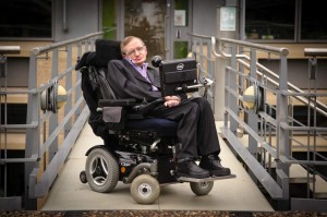
To perform actions there are better methods. If budget issue Hawking students (https://it.wikipedia.org/wiki/Stephen_Hawking) they equipped its super processed helmet Chair. But they tried everything and in the end they chose to look eye-movements with a camera.
With a camera, for example,, eye closure you discover very quickly. With the closing of the eyes you can get four bits of information and many more with eye movements, myoelectric impulses, the direction and speed of the breath etc… With these techniques can easily get tens of bits per second while with an EEG, for how expensive, the response times are of many seconds for a single bit.
For Hawking have done just as well, If you look carefully, in all its recent pictures you see a camera hanging eyeglasses (and in some cases even more experimental sensors).
And now Hawking can speak, Surf the internet and even write books. With the thought would never be able to do all these things.
If there was any possibility of using the thought wouldn't have budget problems. The only wheelchair costs as hundreds of MindWave and EmotivEEG and already had lithium batteries when none of us had even heard of.
Can we do better than the MindWave and EmotivEEG ?
Hate to say it, but we can't. Those two devices have been designed with great care and "trying" to obtain the best possible result. Yet the results are more or less confused (When it's good), and completely random (When the subject is not suitable for).
Subject unsuited? Apologies are always the same, you have to train more, It takes more concentration… In practice to press a button you have to relax completely and then focus for a few seconds. What you should do to write a message? Probably ten years of apprenticeship as a Buddhist monk.
Now the electrodes of a certain quality are all non-contact, but the results are always more or less the same: great instability and no security that if worked today will work tomorrow. Even with 24 endings and big devices with a closet have managed to have decent results.
Active electrodes (first version)
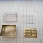
The first version, as from previous images, required a particular electrode with Silver tips. We thank Marco Vitali of: www.vitalibruno.com for having prepared a test enclosure in silver (see image). To make contact with the skin can do no better than silver, even gold is better, and toes help to go hair and to firmly hold the electrode.
Unfortunately, testing has shown that even with these electrodes just the slightest movement to create potential differences of the same order of magnitude of EEG signals (100 UV). To avoid this you have to degrease the skin with alcohol and press much with belt. And unfortunately it also happens that after some time the tips, as far as rounded, begin to annoy. In less than one hour you create markers in the skin which then lasts for a long time.
In conclusion, hate to say it, but this road is not reliable enough to be part of the system Theremino.
Active electrodes (non-contact)
Fortunately during rehearsals with the shell shield and silver with high impedance electrodes we discovered that even with a thin insulating layer between electrode and skin useful signals continued to pass by capacity.
We discovered the non-contact detecting EEG and ECG!!!
As usual, however it is difficult to get there first.
Just search “Do not contact electrodes” on Google…
Non-contact electrodes have many advantages, first of all the complete elimination of the galvanic connection with patient, then security to 100% without batteries or complicated power circuits with safety regulations impossible.
Advantages of the electrodes without contact:
- Total security (the patient is electrically isolated)
- Elimination of complicated isolation circuits
- Eliminate the need to go to batteries
- No galvanic contact voltages for which serves the silver
- Being able to use the copper you do everything with multiple layers of printed circuit board
- Better signal even if the patient moves
- “Zero preparation” (You should clean your skin with alcohol)
- No contact tips
- The flat surface and easier to sterilize
- Functioning even through clothing
- Reduced performance you get even a few centimeters away
- Reduced performance you can make fabric electrodes (moistened only by sweat)
First tests of the electrodes with signal generator
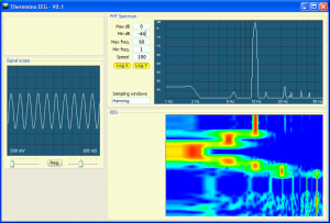
Those wishing to experiment with ThereminoEEG version 1.0 Please download it from here:
https://www.theremino.com/downloads/biometry#eeg
To test it you can use a pin set as input proportional Cap16 and move with a finger. If you move fast you can get beyond the 10 Hertz.
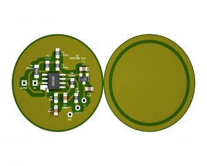
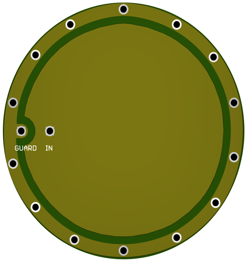
Or sooner or later we will start these new tests PCB. The center circle on the right is the electrode that mates with the skin, the ring (and the back face all in copper that is not seen) isolate it from the environment with an active screen that reduces the effective ability to practically zero.
For the first tests we chose an external diameter of 30 mm and the total thickness is below the 5 mm. Are electrodes small enough to fit comfortably in their place them under an elastic band, but at the same time have very 6 cm paintings of active electrode.
The round shape is a major improvement, it becomes much easier to build them mechanically, and then the containers.
Version 2 – compensation capacity
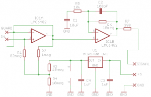
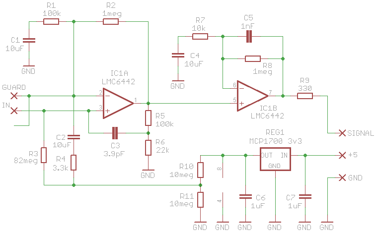
This new version has a more complex compensation circuit, According to the simulations, should improve the functioning even electrodes away from skin. With strong ECG signals you can work even at incredible distances from the skin (10 mm and up to 20 mm with some degradation of bandwidth)
We are doing experiments to determine whether this compensation is actually needed and what are the best values of the components.
– – – – – – – –
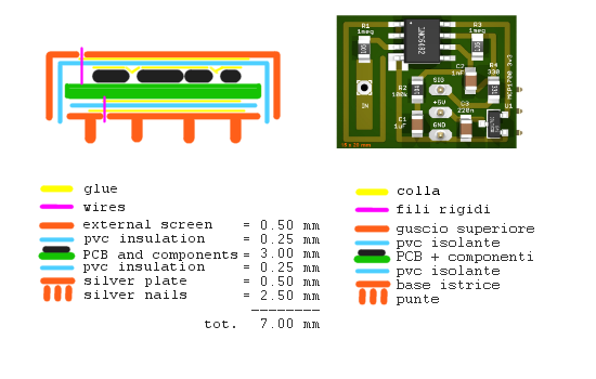
Mounting the sensor
First of all keep in mind that we haven't tested so maybe it won't work right. May not work well or not at all for a thousand reasons, could auto-oscillate or collect power frequency interference to the point of being completely useless. Unfortunately the little time we have is leaving everything to the NetHAL and the NetMaster that will work in network and even in WiFi (but not with all kinds of Master Pin and with a single Adc).
The disc that you see on the left is the face that goes toward the skin. The side towards the skin from now we will call “at the bottom”.
Of course the metallic parts must not touch the skin so it will take even a layer of thin plastic sheet.. A thin plastic like the one of the water bottles can fit. The plastic will “deep drawn” to hot to form a DRAM. Alternatively you might find a exact diameter short and very thin plastic.
The central part of the first disk is a sensitive area that needs to be coupled capacitively with the skin and which is terribly sensitive screen, and then goes as far as possible by electric fields at mains frequency coming from the electric system.
So around the sensitive area is called a ring “on call”.
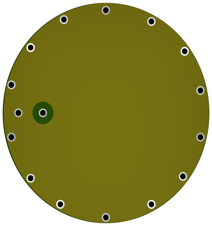
The second disc is the posterior aspect of the first disk and need to screen electrically sensitive zone centrale from components of the third disc that otherwise would pass for ability their signals to record sensitive doing hopelessly autooscillare everything.
Around the first and second holes are metalized disk acting as a Faraday cage and help to shield the little signal that could have come from the sides.
Both the guard ring that the rear face are connected with a small wire which will pass through a hole to be made in silver rectangle “GUARD” the third disc. You connect them to “GUARD” instead of mass because otherwise the ability to ground completely would Dim the signal.
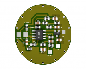
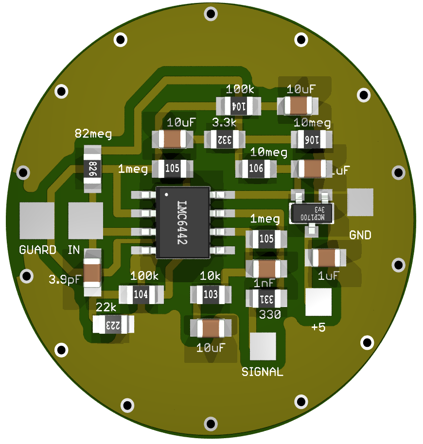
In the next image we see the silver rectangle where you will make the hole where it passes the wire that will be paid to “GUARD” the first disc. And also the rectangle “In” will have a small hole with a small wire that will be paid to “In” the first disc.
We didn't do the holes in plots GUARD and IN the third disk because you thought you mount it with the component side to the first disk and then do double sided with the back completely at the top and connected by copper by holes to its mass. But this Assembly would have made it impossible to do tests. For example,, change a component or solder a tad bit somewhere to make measurements.
Whereby the prototypes (yet to try) We did the third disc to a face alone and assemble with components to high #8217 &; (not to the skin). But be careful with this kind of installation you will have to pay attention to two things:
1) The outer ring of holes are not metallic and then do not touch the outer face of the first disk.
2) That the components will not be left uncovered but you must add a disk “all copper” to shield upwards. This last screen will be paid with a single side wire, so that you can uncover to access components and then close during the functional test.
And finally, at three pitches on the right: SIGNAL, + 5 and GND, settled three soft wire that will go to a Master Pin configured as Adc16.
– – – – – – – –
For those who want to experiment, Here's the project at present (as soon as we have time to improve)
Eagle project downloads + simulations + 3D images
Sensor_NonContact_V2


Thanks for the replies.
I'm going out for a moment from the parent topic giving an info maybe useful, on the supply of PCs.
I wanted a pc powered by CC, maybe even with any battery, the info in the net were contradictory, and no experience guaranteed, Finally after much searching I found a power supply, great a matchbook input from 6 V ( for a short time ) ideal to 8 V up to 24V, ( output, power values of a pc) with voltage extreme cooling, successful use ( for over 1 year ) my desktop pc, now for convenience use in series a second power supply, but energy efficiency is improved, ( from 3,5 to 2,5/2,3 amp/h) I also used a car battery.
The efficiency of these power supplies is ca. of 95% at 50% by use of their resources, That's 125 W and use ca 2,2/2,7 amp/h.
Returning to appliances in question:
Electrodes must not penetrate the skin at acupuncture dfference.
There are limited areas and lines on the skin that depending on the person or his particular psycho-physical conditions of time become iperestesiche.
The use of weak faradic, applied on the surface of the skin is intended to identify these areas.
I am studying this topic and will be completed between 5 months, personal interest, If you expect a development on the subject you can see through the techniques that I acquire as you then interpreted key technique
The current is the most efficient for both find that excite skin, Let's say if you want to stay on the simple a generator just, the rest he does practice and experience.
I downloaded EEG V1 there are directions on how to connect to the master.
With this program and we say suitable sensors, You can find areas of skin with different electric charge, This is the purpose of the project ?
Hi Max,
From what I understand, use a PC which can be connected to a battery, and this is definitely an asset.
However, because the system is secure, It is good to also cure the isolation of the downstream part of the power supply than mass, so the subject under test is not subject to potential differences.
With regard to your search, I understand that you're dealing with traditional Chinese medicine, in its modern electrical implications of points and meridians.
Meanwhile, I suggest you do practical experience on some human subject using information relating to Shiatsu, What that allows you to capture a certain sensitivity to the position of the meridians.
As regards the electrical points, I urge you to be careful. Years ago I tried on myself a small tool specially designed for this purpose, a new electronic magazine kit.
Some points located them painlessly, but for one in particular felt such a shock that I stopped using it forever.
Since then I forced myself to do always much attention before to stimulate current steps on the skin.
As you say, the conditions of the person affect the conductivity of certain areas, and how acupuncturists are well aware, the most sensitive areas are usually the ones to be treated.
EEG reading deals with alternating signals, While in your case (as far as I know) It is more correct to read DC signals.
However, from a theoretical point of view the points could also cause a read alternating current variation resulting from the body's internal processes (brain, heart), but for this purpose I don't think fit the electrodes without contact, not because of the lack of contact but because you need something to read on a surface point source.
I guess I can speak on behalf of the other co-workers by saying that we are available to assist you with your research, consistent with the free time available to us, and only for experiments that do not ever endangered people.
Hello Maurizio,
the skin is the boundary between man and environment, There are doors dedicated interchange, can be activated, According to the mood, According to various external environmental conditions, the hours of the day and night, According to the link with the subject's organs and psychic areas hyper or ipoattive etc.
If the unit worked, It could be that you've touched a point some highly, hard to say now.
If it happened on certain lines, mechanical or electrical action above a certain frequency threshold , the responding.
You have to know which organs and psychic aspects belongs to the point you want to stimulate, We measure the response ( micro-milli amp ) set the unit to a level barely noticeable from the subject, do not Pocket the cute talking is treated with pulses.
An electrical appliance aims to get to the root of the person..
Thanks for availability.
Hi Max.
I see that your knowledge of TCM (Traditional Chinese Medicine) are extensive.
I get the impression that you're a professional operator, not a fan like me.
The interactions you cite (in particular those related to the psychic state) I was quite intrigued, Recalling past experiments.
Using a sensor like the one you're assuming (or more sensors, to monitor multiple points simultaneously), It would be interesting to try to induce psychic States to verify how and to what extent these points are activated.
This could be one interesting idea
http://www.biophysics-research.com/Validazione.aspx
Hello Maurizio,
my interest is personal, the way to know is long in practice, few concepts not make me expert.
In that site there are principles that can be shared, Hopefully, those valid researchers can continue undisturbed research.
First I have to find a schema of Stimulator, or maybe just a stimulator by trade, I need to delve into.
An electrical impulse seems sufficient just perceived and precise control of electric parameters.
The psyche is important as connected to the body, It is remarkable how progress is tiring, the collapse effortlessly, must be a fundamental law life.
Hello Maurizio,
I read a work of 76 by some researchers, including Becker, He spent years in research of psychoenergtic system, they performed measurements on the meridians of agopuntira, resistance & conductivity, repeatable measurement that confirmed the position of the meridians Lin and P.
And’ been used a Wheatstone bridge as a constant source of direct current, the output of the circuit was a direct reading of the conductivity of the skin, quote of the document concerning evidence.
In other cases, there is always the use of Wheatstone bridge (Backster and others , plant size ).
I have Japenese to combine with a tester to amplify the feeling X 10 or X 100.
Purpose try to find lines and points, likely then depend on the used electrodes and connections, thereof between the device and the body.
I saw a device as big as a razor ( to stack ) you hold it in one hand and put the tip on the skin, This once on emnette a continuous sound, Watch your tone when it detects a some point.
Build something similar with display would be fine anyway.
Hi Max.
In a few lines you wrote very. Many concepts, though not in detail, already knew them.
You mentioned researchers with whom you will get many results in google.
Could you give some links to documents you've read, or get it by email?
I would love to help you, but you need to provide more details about the direction in which you want to move.
Build a system of reading the skin resistance, itself is pretty simple, as you have seen there are in network diagrams.
But if you want to build something specific, then we can study it together.
Text read:
electrophysiological correlates of acupuncture points and meridians.
You download the pdf writing the phrase on google, I don't have your email to send you the document.
About other experiences with Wheatstone bridges I reads but not detailed works, I refer to Backster or Marcel Vogel, they used this device even with plants but for different purposes, you notice how they chose to measure resistance instead of the voltage, in the pdf instead measured the voltage also, my interest is to find spots and lines on how is secondary.
Hi Max.
Looking in google's electrophysiological correlates of acupuncture points and meridians pdf” you find the document that you cite, and a series of documents that reference, for the most part, an interesting research done using an array of sensors to peaks, also quoted from the first document.
I read quickly the document you mentioned.
There are no details about schemas used, However contain two different types of readings, Wheatstone bridge with electrostatic voltmeter, this case with readings difficult to perform.
Interesting the part where they say that using voltages above 3 volts for conductivity measurements produce successively reading DC voltage greater than normal for a few hours after application.
And very interesting the theory that physical pain is related to DC signal transmission.
The first thought that comes to me, reading about these experiments, is to use a small robotic arm, equipped with an electrode designed to make no friction on the skin, with constant pressure, you make a two-dimensional scan of a sufficiently wide, so you can then view a color image of map of skin conductance.
Another interesting experiment (certainly easier to do) is continuous measurement of the conductance of a point during physical or psychological stimuli in an area related to the issue, displaying the result on a graph.
But these are my ideas a little classic’ visionary.
What you need, at the time, If I understand, is an easy way to start to locate the points.
With the data available, I would say that you need to use a reader with conductance voltage below 3V.
As soon as I can do some testing using hardware and software system Theremino, to see if I can read something sensible and repeatable, without the need for specific circuits.
But you have to be patient, because I do in his spare time. It may take several days.
Hello Maurizio,
no problem for the time, is substantially the availability.
You should be able to have my mail at the time I had exchanged messages with Livio, If you want I can send the diagram ( I already have all the components ) I found resistance detector, though with Theremino for graphics and flexibility and technology would be much better, at your discretion, Maybe you could try for a comparison, as long as it is technically sensible suggestion.
I can confirm that a direct current ( I have to inform me on the output voltage of the electrodes ) generates an electrical response on the lines or points ( potentially ) iperestesici measured in micro/milliamps, This indicates if the underlying psychological and physical bonding is ipo or hyperactive.
To have constant pressure, you could also use some fixed weight imposed upon a wheel with the handle to move it on the skin.
If I can build it.
About the pain let's keep it in abeyance as an argument, I svaruiate personal experiences.
I share your visions, Temo's for nonconformity to clarity, the male pierces the mists of the unknown using quality provided by mother nature.
The fantasy, precious dowry in artists where probably is free to ride, the scientists and researchers is then taken by the hand by reason.
I confirm,Ideally, a simple device ( always that simple is synonymous with effective ) that shows a difference of electrical parameter or otherwise between a point known as some compare him to another neutral.
In this year and a half I had to catch up on many subjects. I'll start with the experiment # 1 Brain. Any criticism or suggestions are welcome. Thank you. Kind regards.
Domenico wrote:
With the system Theremino you can detect very low frequency electromagnetic waves in the environment, Let's say from 0 Hz -100 Hz, and maybe with a response from the entire spectrum in real-time?
I'm experimenting with Spectrum Lab, but I can't find an interface system, specific to intercept these frequencies. I don't know if you have created something similar with the system Theremino, or give me directions about.
Answers:
This feels electromagnetic fields up to 300 Hz with very high sensitivity:
https://www.theremino.com/hardware/inputs/meteorology-sensors#emf
It also has a logarithmic output, as explained here:
https://www.theremino.com/technical/tables-and-notes#scales
Then measure, in a single range, from the weakest to the strongest.
Be aware though that the antenna should be made specifically (with adequate size) It must be a coil or a stylus, Depending on whether you want to detect magnetic or electrical fields.
However, this circuit does not distinguish the frequencies and produces a single value that is the sum total of all disturbances in the useful range.
Instead your words suggest to do the analysis of spectrum and this idea is very interesting because it would read more info, but most of all because it would not be fooled by the omni-present 50 Hz mains.
Spectrum analysis with sound card and DAA
——————————————————————————————
Or you could attach a reel or rod antenna to the microphone input of any sound card. Then raise the maximum input level and finally use the DAA to make spectrum analysis.
https://www.theremino.com/downloads/uncategorized#daa
EEG spectrum analysis with DiffMeter and Theremino
——————————————————————————————
Or you could connect the DiffMeter to a rod antenna or a coil and plug it into a Pin configured as Adc16
The DiffMeter will be set to low common-mode (+/- 3.3 Volts)
https://www.theremino.com/hardware/inputs/sensors#diffmeter
by setting values as follows:
– R3, R4, R5 and R6 = 10 Mohm
– Trimmers from 470 Kohm
– R9 by 0 ohm up to 150 k depending on the required sensitivity
Then to make the Theremino you could use the EEG spectrum analysis that is designed to control the electrodes of electro-brain-cardiogrammi, but it is also perfect for all kinds of spectrum analysis, the low frequencies.
https://www.theremino.com/wp-content/uploads/2013/05/Theremino_EEG_V1.0.zip
https://www.theremino.com/blog/biometry
The Theremino EEG currently reads only the slot ZERO, so you have to set the Pin of ADC to write on the slot "0"
Spectrum analysis with DiffMeter and Max/Msp
——————————————————————————————
Once the signal is read from DiffMeter and brought on a Slot by ADC, It would also be possible to divert it to external programs like Max/Msp…
https://www.theremino.com/downloads/foundations#maxmsp
Or to programs that can communicate over UDP with OSC letters
https://www.theremino.com/downloads/foundations#osc
Then theoretically also Spectrum Lab should be able to read our data. But we don't know him and so we don't know whether it is possible to equip it with a PlugIn or something like that, to read our slots.
Here's my experience. From the beginning I have always struggled with the size. Before the mm, then the tenths,then the hundredths and thousandths. The catch was always the same: connect 20/40/100 pins of the chip to external components. Passive smd sizes were and are huge compared to the chip. For my applications I chose Microchips and Texas. The first for the cost, the second because it had more choices of micro with analog inputs. But the problem of size still remained and forced me to constant compromise and exasperated circuit. Manufacturers build their chips on the basis of market demands, especially automotive, Mobile etc. I had always, in each component, or a lack or surplus of performance. I had an idea. Ask manufacturers to put on a single chip the functions of other. Basically assemble standard functions on one chip. The answer is "Yes". Aside from the costs, the main reason why I didn't go ahead was legal. Meaning that if your application request by me was a success, the Builder appropriated the project without pay anything. As for ECG and Wearable Sensors typically, If you look on Texas are any components with its application. There are also wireless chips and many other useful components in order. Assemble them in single chip would be great. Obviously
before you make the evidence for example with Theremino to develop the project, then you choose the components. In the end though it lacks an important element which is the doctor. Does any one but a University researcher who knows maybe even quantum physics. If you have news of any body sensor, not to assemble, I will be grateful if you wireless or Bluetooth you will communicate. Greetings and thanks. Joseph.
Good evening, I am a young student who is developing a simple BCIV for a school project. I would particularly like to delve into the software used to process the signals. As has been written? Which methods of analysis were used and how they were a ti implemented?
Thank you in advance.
What is “a simple BCIV” ?
The Theremino system software are all written with Microsoft Visual Studio DotNet.
Software information and tips for developers are here:
https://www.theremino.com/downloads/notes-on-software
I can not associate Theremino V4 module Theremino_EEG _V 1.0. In other applications, it works. Tell me what’s the problem ?.
Theremino EEG is a simple and experimental application and so…
1) The HAL application is not included in the Theremino EEG zip-file.
2) The Theremino EEG application does not starts automatically the HAL applicaton.
3) The input slot is fixed to the slot ZERO
You can try EEG changing the slot zero value with the SlotViewer
Then you have to download the last HAL application.
Then you start the HAL application manually and set the ADC Pin parameters to the slot ZERO.
In the future you could also start all automatically, as explained here:
https://www.theremino.com/en/downloads/foundations#starter
Thank you.
Good morning,
Theremino DIL-V3 master might measure the frequency of an electronic board ? It is low frequency 1 to 1000 Hz splitting the measure must be of 1 Hz. because if I need to be able to see for example rule 357 Hz or 249 Hz.
Since I would also see the waveform of this card can be used as an oscilloscope ?
You sure can measure a frequency.
Attention only to not send too much tension (beyond the 3.3 Volts or below zero Volts) with too much current (In addition 100 UA). The inputs are protected and do not break, but may break the USB transmission. So it is good to add a resistor in series with the signal, placed next to the input pins of the Master. A 10 k resistor is fine until a few volts too. If you have very high voltages 12 volts or more. then you should use a 100 k resistor or an appropriate divider.
All pins of all versions of Master, and even the slave “Servant”, can be set as “Counter” and then set to measure the frequency. Try it even if you get more precision by setting them as “Period”.
Some special Pin can be set as “FastCounter” and measure frequencies even high enough (up to 50 MHz)
Here shows the Pin that you can use with the various versions of modules:
https://www.theremino.com/hardware/devices
Here are long explanations for all types of pins, one by one:
https://www.theremino.com/technical/pin-types
See the signs
—————————————————
To see the shape of the signals you need to set the Pin as ADC16. The same considerations already written on the maximum voltage 3.3 Volts, as well as on any resistors or voltage dividers to add.
Then you should also write some software, a small oscilloscope.
Currently the only application already written that does something like this from a Slot (and only from slot 0) is the “Theremino EEG”, that you download from this page:
https://www.theremino.com/blog/biometry
With a few tweaks you could turn it into a more complete oscilloscope.
A true oscilloscope
—————————————————-
To get all the performance of a true oscilloscope, and also a more precise frequency measurement, You should use the Theremino DAA that you download from here:
https://www.theremino.com/downloads/uncategorized#daa
But be careful: If you use the DAA the signal must come from the sound card. Then the Master and the HAL are not used!
Good evening,
Let me start by saying that I made a counter gaiger theremino system extremely reliable and therefore I commend you for the many insights you offer.
Now I wanted to experiment with e-meter and lie detector. It's not clear to me, however, in the project e-meter what kind of sensors can be used.
Thanks again and keep up the good work
Carlo
Hello Charles.
In fact, I checked and in the downloadable version of emotion meter there is documentation on the electrodes.
Intentionally, the application name theremino is emotion meter, to differentiate it from the devices you citi, used by a well known Association.
Unlike those systems, the theremino emotion meter is based almost exclusively on software.
At the time, the project is stopped, but we can certainly help you if you'd like to learn more.
I've taken care of me for a while, but I could not reproduce the behavior of the original machine, I had seen him in action many years ago, and I've had no time to do other experiments, that would require, inter alia, the use of volunteers for testing practices.
Original device electrodes were two cans of tinned iron (in the years 80 stranded very easily by removing the paper label from cans of spray paint).
Years ago I tried with other materials, and I did other tests recently, When we began the project emotion meter, and I can tell you that the electrodes in different metals from tinned iron malfunction.
Modern devices used by the Association, and other independent operators, use electrodes in plastic coated in silver, that seems to be currently the best solution.
The electrodes are held in the hands, impugnandoli as the knobs of the bike, but in an upright position. The subject must not wear rings or other metallic materials that may be in contact with the electrodes, Why would produce distorted measurements.
For connecting to the master theremino, the first tests were made by connecting a grounding electrode and one to an input, with a pullup resistor.
I remind you that this system can become potentially dangerous, Since the subject is connected to an electrical system through a low-resistance electrodes to the skin.
To ensure the safety, You must have all the system functions to battery, and you need to be sure that the maximum voltage applied between the electrodes is very low.
For this reason, the original machines worked exclusively with rechargeable battery, and it was not possible to use it while charging.
Let us know if you need more information about the tests.
Hello
Maurizio
Hello, I'd like to detect brain signals ,theta alpha beta gamma delta waves which then would correspond to various Hada States ranging from waking to sleep or meditation. You have already done something about it ? Once there was a brain olotester that gave a clear picture of all levels of signals I mentioned, by examining their consistency…It would be fascinating to be able to do it with theremino!
Thank you
I would respond by recalling this information:
https://www.theremino.com/blog/biometry
The information you showed Claudio are an important prerequisite. You don't have to wait for the impossible. If you agree to the limits set out in those premises and you think you can the same get something useful, You can try this system:
https://www.theremino.com/downloads/biometry#mindwave
I have not explained well… I don't want to operate devices in thought but just read the signals emitted by the brain ranging from a few hertz to approximately 13 Hertz…
The headset mindwave (the hardware part) does exactly what you say, that is, read the signals ranging from a few Hz to a few tens of Hz.
Then our application “Mindwave bridge” allows you to read the signals coming from the headphones and get numbers on your PC (more precisely into the slots of the system theremino).
https://www.theremino.com/downloads/biometry#mindwave
Good evening, are interested in experiencing the electrodes without contact version 2 , could you help me to understand how are assembled and connected the two printed circuit boards, I have found no indication in this regard.
Any other further indication about it, It would be a beautiful gift.
Thank you.
Franco
Hard to explain in a post like this for which we have added images and text best we could write. I hope you can be of help. Hopefully we will complete upon request to clarify details that are hard to understand.
Anyway, remember once again that there is a good chance that not work. It is a difficult project, the input impedance is almost endless. You may have all kinds of defects and to solve them it would take a lot of experience with such high impedance circuits.
Thank you very much, I try anyway and if you don't bother, I would like to inform you about any obstacles or successes.
Thanks again.
Do not disturb for sure, only regret not being able to do more to help you. Did you see the new images and text? There is something you don't understand? If write us as well and we'll try to improve it.
For the moment it all seems clear, during construction possibly write to you.
>Thanks again.
Hello everyone. Any news on the skin with the resistivity measuring system Theremino? I discovered the Internet open source software LedaLab. Is a MatLab plugin for which I think it's not immediate application and use. Does not make reference to any hardware for which I do not know how to capture data. On a screen on the site LedaLab it is understood that processes the data a txt file but how to acquire them? I realized the spectrometer (fantastic) and I'm applying on CapSensor, I would now like to orient myself on biometrics. Let's see if you have any big surprises under the tree for us avid fans of the system Theremino !!!
Measure the resistivity is fairly easy, even with an input on the master set as Res you can get stable enough measures. The only flaw is to have one side connected to GND and then having to use a Tablet or a Laptop not connected to the network.
Wanting more precision you could send a constant current between the two electrodes of low intensity. Measure the two tensions with two inputs Adc16 and subtract the two values measured to obtain the difference. You could get a simple generator with two resistors 10 ... 100 k one to GND and one towards the 3.3 volts.
Wanting an even more precision you could use a Adc24 module that has true differential inputs and filters that you can get an almost total common mode noise cancellation.
The data may then be logged and then see them on other applications (probably also Ledalab). You could for example use the Logger
https://www.theremino.com/downloads/foundations#logger
Or you could view them and simultaneously loggarli into a file with the SignalScope
https://www.theremino.com/downloads/foundations#signalscope
Hardly we will publish an application like Ledalab because we don't know anything about the topic and we're extremely busy with new products (Arduino WiFi modules and modules) We would like to get for Christmas, but that… you do what you can.
If you want a really useful and interesting news, who has relationship with biometrics and built in ten minutes, I suggest the FlickerMeter
https://www.theremino.com/downloads/uncategorized#flicker
Thanks Livio. Always very exhaustive and precise in answers. I already have the Adc24 module and try for sure. Having multiple inputs maybe I can place multiple sensors. Detection of GSR (Galvanic Skin Response) is very influenced by the pressure of the electrode application. Our nervous system controls the skin with a modified sweat gland secretion and thus skin resistance under any detection electrode. This expresses the phasic activation of the autonomic nervous system on an underlying tone. This is just what LedaLab. Actually it would be better not to measure resistance but rather the real humidity level with microsensors. The thing is complex. Better still would be to resort to photosensors to 265nm working in reflectance but what here should be taken off the component of the reflected light from the stratum corneum using a polarizing filter as is done in vivo spectroscopy systems (Antera3D System). So it seems easy …. but it didn't seem really so. I knew of your news because I got off the phone with MaxTeremino and quiet aspect to see them posted here. I promised to send a photo of the spectrometer assembled as soon as I get the excitation laser. Thanks for the tips. I thought it might be of interest to other my request and this is why I posted in the blog. Best wishes
Best wishes!
And Merry Christmas to all thereminomani,
and thereministi (who are the ones who play the theremin),
and to elettroamici who are the friends of https://www.elettroamici.org
Will not distribute a mail with reindeers but we'll use the time to write software documentation. See the what's new page frequently and in the next few weeks you will find our Christmas gifts.
Hello Livio.
After a few months I go back on topic “Biometrics” for a suggestion for new releases (When there will be) Theremino ECG system. The question is simple: I see that the system makes it possible to measure the average heart rate calculated over 1 minute (Heart Rate), but soft screen Theremino ECG appears (between a heart beat and the other) the figures of the time elapsed in milliseconds. This is a very important measure because it allows to measure the Heart Rate Variability (HRV).
Looking at the graph of the track released in your site the HRV you would measure so:
(796-804)^ 2 = 64
(770-706)^ 2 = 4096
(728-770)^ 2 = 1764
In practice it squares the difference in milliseconds of elapsed time between one beat and the next. It becomes clear that the heartbeat (as average rate per minute) can not change (or change slightly) in a minute and the next (in the picture published in HR = 82/min), but the variability of duration between different beats varies greatly (64, 4096 and 1764) !!!. I think the strattagemma of to square the result is made to always get positive numbers of HRV.
This is quite important in electrophysiology and allows you to see many interesting things about the balance between the sympathetic and the parasympathetic system that monitors heart activity.
I wish you and others read this reference of which carry the link (but there are many others on the WEB):
https://www.selfcoherence.com/blogs/no-stress-blog/variabilita-della-frequenza-cardiaca-heart-rate-variability-hrv
Well, Once you have a marathon series of HRV values (one for each pair of beats) These are facts “Digest” from a soft which makes the analysis over time so you get maximum expressivity of the data obtained. Changing from lying to standing heart rate changes, but his variation is absolutely less expressive than the HRV (you bring out subjects with answers VLF, LF and HF). Even the most diverse biological stimuli and emotional States affect HRV and its spectrum analysis.
Morals: the acquisition of an ECG is definitely nice and useful thing, but its integration in a given again as the HRV is absolutely greater utility and DIY spirit.
I understand that programs are “open source” and then that hacking you could get the HRV so not difficult, I don't know yet how to handle the Fourier although you have posted the soft signal analysis. I really don't know which way to get it back.
Thanks for the time you'll spend and hope that the post be an incentive for someone else.
Hello Lorenzo.
Long ago I was interested in the HRV, but I had found only background papers, No in depth.
I am very interested in the subject, and I see that you've managed to deepen.
I would like to start a debate where you can explain in details what do you got, and what measures and calculations put in Theremino ECG.
I can't speak on behalf of Livius, that is very busy and has its priorities, but I can help by talking to you, and in this way understand in detail what changes to make to the program, to put them on the list in future revisions.
I invite you to join the site elettroamici, where we can open a discussion, and where I'd like you was publishing an article informative on the subject.
Hello
Maurizio
Sounds good. You could do the research and distill the formula to use and the data to be submitted. I won't have time to follow this subject for at least a month or two.
Anyway for tests you don't need my speech, and probably change the ECG application would not be a good idea.
ECG emits pulses on a slot and the BPM on another (the bpm are the inverse of time), and with four lines of software in any language you might calculate the HRV.
Among the most suitable languages there's probably Excel, It would also present the results in charts and tables. Or a small application in VbNet. And if you need spectrum analysis just copy it from many of our apps that already do it (for example WaveAnalyzer).
An article on Elettroamici would be a great idea!
Maurice and Amilcare (Elettromici administrator) will help you get started and then you will have a space all your own, where to publish every new idea.
Also the forum on Elettroamici is better than this blog, the editor is better and the arguments are all well separated, each with its pages and its title.
Makes me absolutely no pleasure to have stimulated your interest. You need to spend a little’ of time on this topic and so I have to program the system to have it available. I'm already subscribed to the blog of Elettroamici but I have little time to be “Active”. It is necessary to establish a road map to operations and I think a direct contact with Mauritius may be necessary. How do you in this blog? You can enter your phone numbers or are asked to be contacted on email indicated below?
You can do as you wish, But if you do not want your information to be displayed is better than sending mails with your data.
VITTORIO CI CLAIMED
I would build a detector of electricity, I'll explain and give an example so we understand each other better. In a house on the roof (I eye 15/20 Mt) pass the wires of 132KV. then I lay out a dish (insulated power cable) above the tiles and I could use a tool that could detect the slight variations in voltage.
REPLY
The three wires 132 KV radiate both an electric field and a magnetic field.
Electric field
It can be measured with a wire "antenna" isolated, suffice a few meters of cord from electrical system. If the signal will be poor stretch the wire, if it is too strong it shortens.
No matter if the wire is covered by the insulation, indeed it is better, so moisture does not oxidizes. Both the AC voltage is coupled capacitively through the insulating coating.
The thread must be kept at a distance from the roof (I would say at least two meters above) otherwise when the roof is dry measure more and when moist measure less.
To make a descent in the house you should use a shielded cable with the shield grounded, otherwise also measure the electrical system radiating home.
You can measure the alternating voltage with a tester positioned in Volts AC between the wire and a ground socket (or a water pipe)
Needless to measure with your PC, you just measured once and for all. Both the electric field will always be the same, It is given that the voltage is fixed at 132 KV. Any changes will be due only to changes in humidity or the wind which moves the antenna.
Magnetic field
It can be measured with an enamelled copper wire coil.
I would start with a few hundred of turns and then aumenterei the coils up to thousands if the signal is low.
To increase the signal could also add a core of ferromagnetic material open at both ends (in practice with a bar above the wrapped wire)
You could use a transformer (the primary of 220) but opening the pack of laminations (maybe let the plates but have them straight, removing the reclosure of the magnetic field).
The coil may also be close to the roof and also under the roof. But it goes farther tight as possible from mains electricity supply wires.
The measured magnetic field will change depending on the current passing through the high voltage wires.
To make a descent in the house you should use a shielded cable. In this case no use that the braid is connected to the ground and the risk of both disorders that lightning is less.
You can measure the alternating voltage with a tester positioned in Volts AC between the center of the shielded cable and the braiding.
Measure with PC
Connect the central wire of the shielded cable of descent to the soundcard input (O THE MIC)
Better to use a USB Sound Card, which it costs a few euro and then even if you break your changes.
Consider that especially in the case of the antenna for the electric field are creating quite a lightning rod connected to the PC. So it is good to put two 1N4007 diodes, in anti-parallel between them, between the center of the shielded cable and the mass.
The signal must pass through a small resistor 10K positioned close to the sound card (the resistor further protects from lightning and also serves as a fuse in extreme cases).
The tension to be sent to the sound card (to be measured in advance with the tester) It must be in the tens or hundreds of millivolts, up to a maximum of one or two volts AC.
On the PC you will use our application Theremino DAA to make the measures.
Measure from a distance of 15 or 20 meters
Both in the case that electric magnetic, I do not know if the signal is strong enough to be measurable and distinguishable from the mains electricity supply, which it is definitely stronger.
In any case, before doing I would try complex systems with some meter of wire (or a coil) and a tester, and what signal is misurerei.
The tester in Volt AC fit well even very low signals.
Hello Livio.
The reading of your speech reminded me of some schemes of radio receivers with transistors exclusively fed by the signal present in the antenna, provided of course have a very long wire antenna and at least one transmitting station with high power not too distant.
Unfortunately, I do not remember where I had seen those patterns, that worked with a germanium transistors that can be powered with a lower voltage with respect to silicon.
I searched the internet some scheme, and I found only this
http://zpostbox.ru/fm_crystal_radio_receivers.html
a Tuscan ham radio, which not only uses two silicon transistor, but also it allows you to listen in speaker, all powered by the single antenna, inter alia so small yagi.
Following some personal experiences in a house in a line from 380 kV, I believe that under high-voltage cables is possible to draw sufficient current to operate small electronic devices.
Let me advise you to pay close attention to the tension generated between a long wire, as proposed by Livio, and the Earth, because I remember from my experiences that a wire was not too long enough to feel a nagging (and almost unbearable) shock by touching the two sides with both hands. And it was not a static which is discharged in an instant, but a stable current in real time.
I believe that a collection system consists of a long wire, or by one or more coils may even turn of small LED lamps.
I wonder if this is lawful removal of electrical power.
If the energy supplier passes overhead high voltage lines, and with these radiates our property, It may object to the fact that we use this irradiation?
Or is her business, and if he does not want to use should be the entity that avoids using radiate shielding?
And the energy levy through a coil of the line increases the transmission losses, or we collect only part of the inevitable losses?
Hello
Maurizio
Following further research in English, I found this thread
https://electronics.stackexchange.com/questions/124765/tapping-energy-from-high-voltage-ac-transmission-lines
where clearly they warned to be very careful with the voltage that is generated in a wire under high voltage lines, because it can reach the tens of kV.
According to the author, the levy made in this way is illegal, but I remain doubts about this topic.
Hello
Maurizio
Can you get to high voltages but only with open circuit, as soon as it loads with a minimum of the voltage current drops to zero. However, we await evidence of Vittorio.
Surely lawful! They just can not radiate.
The levy affects a little’ on losses, but such a low quantity that is indistinguishable from the variations, thousands of times more, produced by trees that move and variations in humidity. Anyway all “picks up” energy and heats up a bit '. Not just our little trickle but also the roofs, trees, the terrain, cars and people passing below.
Regarding the withdrawable amounts would not be, however, very optimistic. It is also necessary to mention that a good part of the field is cleared for opposing currents and voltages in the wires that pass. So tens of meters according to my intuition will not be very.
The author of the post is about a transformer to bring the voltage from a few dozen kV to 120V, and then turn on a lamp from 4W, which we are not few because we are talking about energy recovered, inter alia, considering the losses introduced by the transformer.
I agree with the view that it is the manager who has to worry not to irradiate, but I also believe that if someone has an extensive ground under the regaining power lines, the manager would not be good and quiet to see.
Although from my point of view it would be the history of the poultry shop owner who demanded a payment from the person who ate a piece of bread out of the shop smelling of roast chicken…
There is definitely a distance from the wires beyond which you can not approach, otherwise one might raise in his ground a tower (for example wind turbine blade) with great danger to those who work there, and that in case of rain could even produce huge arcing. So if the antenna closer to the wires, beyond what is allowed, they will tell you anything.
In addition, are taken and that he was not la, the same energy will be lost in moist soil, heating it slightly. The land is immensely larger than any antenna can be conceived and “consume” from the power line million times the energy that we consume with antenna.
The losses are expected in the power line project and inevitable. So if someone uses it and does not let heat the ground it is only an advantage for all mankind.
Hello, there is no one who has technical elements to make a electroacupuncture of Voll or better detect signals Bioresonance? There are complex and expensive equipment ,SICOM, MORA, Bioexplorer etc.… I would love to be able to do even a tenth of these devices…if anyone knows a bit this industry come forward, I'm sure that you can avail with Theremino do so much!
I have no experience on these devices but I can give you two ideas on what to use:
– If the required accuracy is not much (about one part in a thousand) just do a little input interface for the Master Adc16.
– If you need to measure very small changes need a high precision, then serve the Adc24 module to be connected to the Master. The Adc24 is accurate (about one part in a million) and can also make differential measurements.
In both cases the interface may also be very simple, such as that del'EmotionMeter that measures the resistance with just two components:
https://www.theremino.com/downloads/biometry#emotionmeter
good morning to all of you. I'll be back again on the subject HRV (Heart Rate Variability) I have “evoked” the 3 June last year. The argument gets more and more development in science and after measurements made over long periods of time (24 hours) It seems to have not the expected predictive value on cardiovascular risk assessment as a whole, those made over much shorter intervals (5 minutes) if interpreted in spectral analysis really have an important biological value. The scientific literature indicates the possibility that the HRV can be a good indicator of >emotions< e addirittura che possa misurare l'intensità del dolore percepito. US researchers have developed a system for MEASURE pain through changes in pupil size (dilation of the pupil has to increase in sympathetic activity resulting in their pain); similmente l'incremento della sudorazione cutanea esprime l'attivazione del sistema simpatico ed è rilevabile misurando la conduttanza della pelle con il GSR (Galvanic Skin Response). Interesting reflection on important points that are taking the HRV can be found at the following link https://hrvcourse.com/heart-rate-variability-vs-heart-rate/
Non ho la preparazione per modificare le linee di programma del vostro Theremino ECG o dell'Emotion Meter (the extent to which the fine GSR … I tried!!), nor incorporate Fourier … but perhaps it will not be so difficult for any of the players or the administrators of this useful web space that will offer us a solution!.
Grazie comunque della attenzione e per l'esistenza di questo sito dove apprezzo tutta la vostra competenza.
This is a research suited to Maurizio. If he sets something raw and explains how, then we could “put it in plain”, as we did with the Emotion Meter.
Good morning Lorenzo.
I am interested in the HRV some time ago, without significantly into that.
The only practical use of which I was aware of was to avoid over-training in athletes.
The developments you mention regarding the extent of the autonomic nervous system are very exciting.
In the link you posted say it is better to have a high HRV at rest, and a low HRV during exercise. It is only an apparent oddity, But think about it is logical..
In the same article point out that under the term HRV are grouped different analysis methods, and that some of them are suitable for the measurement of the autonomic nervous system.
My first impression is that this topic lends itself to research and very interesting insights, and that there is still much to discover.
The work takes me away most of the time, so I have no way to participate in depth in this topic, that still interests me very.
My contribution at the time can be more of an expression of my views about.
Among other things, my skills in the use of complex mathematical programming in VB are indeed scarce, Livio and this is very good.
I am not in agreement with the cutting of the article link, which compares two different methods as the measurement of HR and HRV. We are talking about a single organ, and separate the two measures is absurd, especially given that one is based on the other.
I think you could get very interesting data integrating, and maybe then associating blood pressure.
Flying a little’ with creativity, also the measurement of the derivative of changes in GSR could be integrated.
But remaining in cardiac measures, I propose a collaboration.
If you take care to retrieve details about the various measures to be carried, I take care to think about how they can be used and related, and then pass the information to Livio who is good at implementing them in VB program.
If you write to Livio, he'll give you my email address to eventually communicate directly, but I would prefer that the topic was addressed in a forum elettroamici, so share is the path that any developments and applications.
I agree with Maurizio, it would be better to continue the discussion on Elettroamici where you can add pictures and files. In case you need to explain yourself by your Amilcare how do.
I saw that there are many in the network information in Italian, some of which explain some’ more in detail.
In particular, I find it interesting this page
https://www.selfcoherence.com/blogs/no-stress-blog/variabilita-della-frequenza-cardiaca-heart-rate-variability-hrv
where they speak of analysis in time and frequency, describing different frequency ranges and their meanings.
Thanks Maurizio of having done this study. Add some more info: in the years 90 Holter ECG showed this parameter on 24 Registration hours thinking it could be a matter of importance for the cardiologist. Now the HRV has lost its prognostic value and seems relegated solely in the field of biofeedback. You will find many articles on the web with the parameters to be measured for the HRV. Maybe I try the links and public them here in the next few days. The key element however is the analysis carried out in time over short times ( from 1 to 5 minutes). Having seen that the Theremino ECG has an algorithm for determining RR interval I could say that's it … that is in fact the most delicate phase. The method does not work as well in photoplethysmography (PPG) where the variables are much greater. That's why last year I opened a post on the subject. But my job does not allow me to have time to write an article about ELETTROAMICI like you asked. I believe that an implementation on Termino ECG for you is not very complex … I'm just a fan of electronics for many years but I have no basis to do much. Ok this … but … then what is the determination of HRV although recreational purposes? I have a GSR and professional PPG and use it to perform the effectiveness test of cosmetics and cosmeceuticals. In the measures that get is incredibly evident the activation of the sympathetic nervous system as a measure of arousal of the subject under study. The measures are quantitative, but the soft does not allow to have Fourier transforms … My curiosity to deepen with the measures is endless! Thanks for your time.
Ok. Meet me on ELETTROAMICI! Tomorrow I register.
Hello Lorenzo.
Finally I managed to start a discussion Elettroamici, Electronic Forum / microcontroller / Theremino.
Appearance your posts!
Very well. We'll see and we feel them
Hello, but for the measurement of blood pressure ,you to know, no sensor exists?
Thank you
Hi Angel.
Look here
https://www.elettronicain.it/blog/2018/04/26/ams-introduce-un-progetto-di-riferimento-per-sensore-di-pressione-sanguigna-senza-bracciale-gonfiabile/?highlight=hrv
Hi Angel.
I've been doing lately a search in google on this topic.
Apart from the measures through a needle directly into a vein, obviously used only in the surgical field, and by trained and qualified personnel, the only way to measure the blood pressure is the use of an inflatable band to be rolled over a limb.
There wristbands, that apparently are more comfortable, because it is like carrying a big clock, but in reality they are unreliable.
The best accuracy is achieved with the use of armbands.
There are version-end that have an integrated data logger, and can communicate with a mobile.
At the time, I have seen no development system to integrate with Theremino, but I do not exclude that there might be, and Livio, the creator of Theremino, it has not yet found.
I have done this research for possible future use in an integrated measure with EKG measure of variability, but at the moment I do not have the time to delve.
The pressure gauges contain a pump and a tube that goes to the band. Connected to the tube there is also a pressure gauge that could be connected to one of our ADC (with some part to fit).
But you have to take into account that are not continuous measures. We have to inflate the band (at least ten seconds), and then stand still during the time of deflation (twenty seconds). In addition, the pressure on the arm (or wrist) is loud and annoying, definitely not compatible with continuous measurement, during workouts or athletic performance.