
")
Il Theremino_MCA pur essendo completamente Freeware e OpenSource è un vero Multi-Channel-Analyzer da laboratorio.
Ulteriori informazioni:
– Schemi elettrici e piani di montaggio: www.theremino.com/technical/schematics
– Software: www.theremino.com/downloads/radioactivity
– Hardware, autocostruzione e kits: www.theremino.com/contacts/producers
– Immagini e Video: www.theremino.com/video-and-images
– Articolo su Elettronica Open Source: tecniche-di-condizionamento-del-segnale-spettrometria-gamma
——————-
Hardware per la Spettrometria Gamma


Il Theremino_PmtAdapter contiene un circuito di retroazione in grado di mantiene la tensione stabile anche in presenza di forti variazioni della temperatura. In questo modo la taratura rimane precisa nel tempo e le righe degli isotopi non si spostano e non si allargano.
ATTENZIONE: Per ottenere le prestazioni ottimali è necessario usare tubi PMT cablati come indicato nel file PmtAdapters.pdf – I tubi PMT a bassa impedenza (con resistori da 1 mega o addirittura da 560k) non possono funzionare con questi adapters. Per utilizzarli occorrerebbe sostituire i loro resistori come da noi indicato.
Questo adattatore può essere usato con il ben noto software freeware PRA (ringraziamo Marek Dolleiser per aver aperto la strada a questo genere di analisi, il suo software PRA è un riferimento da molti anni e ci ha aiutato molto) ma solo con il Theremino_MCA si possono fare operazioni di filtraggio e di cancellazione del fondo utilissime per ottenere il massimo di informazioni in tempi ragionevoli.
Questo file comprende il progetto del PCB, le immagini e le simulazioni SPICE: PMT_Adapter_V3.1
Questa è la versione 3.2 con molti piccoli miglioramenti: PMT_Adapter_V3.2
Questa è la versione 3.3 con ulteriori miglioramenti: PMT_Adapter_V3.3
Most salient features:
– Compact only 50 X 70 mm
– No initial thermal drift due to the feedback loop.
– Adjustable voltage from 500 to 1500 V
– Very low power consumption only 10 mA @ 5 V
– Very low ripple only 100 uV
– Protected against short circuit
– Maximum power output 100 mW
– Preamp circuit and pulse enlargement (from 3/5 uS to 100 uS to be read by a PC sound card)
Caratteristiche tecniche:
– Compatto solo 50 X 70 mm
– Nessuna deriva termica iniziale grazie al circuito di retroazione.
– Regolabile in tensione da 500 a 1500 V
– Consumi molto bassi @5 v solo 10 mA
– Ripple bassissimo solo 100 uV
– Protetto contro il corto circuito
– Potenza max erogata 100 mW
– Circuito di preamplificazione e allargamento degli impulsi incorporato (porta gli impulsi da 3-5 uS a 100 uS per essere letti da una scheda audio del PC)
La costruzione semplice e ordinata riduce i difetti di costruzione e li rende immediatamente evidenti.


Nelle seguenti immagini si vede il PMT durante le prove.


Lo schema elettrico e un impulso di esempio che mostra il livello di rumore dell’alimentatore, notare che si tratta di un impulso di bassa energia.


Nelle ultime versioni di PmtAdapter il rumore è inferiore ai 100uV. Praticamente il solo rumore dovuto al campionamento a 16 bit della scheda audio, come visibile nelle due immagini seguenti.


La prima immagine mostra il rumore della sola scheda audio, la seconda il rumore con il PmtAdapter collegato.
——————-
Il sistema completo


———————
Il Pmt Adapter non è in produzione, è possibile costruirlo ma contiene un certo numero di componenti speciali, difficili da reperire e costosi. Per cui si consiglia di rivolgersi ad Lello, che sa come reperire i componenti a buon prezzo e ha anche fatto stampare un certo numero di PCB per gli amici: ufficiotecnico@spray3d.it
Il team del sistema Theremino si occupa solo di ricerca e non vende hardware. Il sistema é completamente “Freeware”, “Open Source”, “No Profit” e “DIY”, ma esistono produttori che possono fornire i moduli assemblati e collaudati a un ottimo prezzo. Difficilmente si potrebbe auto-costruirli spendendo meno. Per un elenco dei produttori leggere questa pagina: www.theremino.com/contacts/producers
Uno zoccolo per il PMT Hamamatsu R6095 (e simili)


In questo file ZIP il progetto completo Eagle e il file GCode per la fresa: PMT_Socket


Queste immagini illustrano come adattare i connettori allo stampato e come viene lo zoccolo finito (fare click sulle immagini per ingrandirle)
Il condensatore potrebbe anche essere saldato dal lato opposto (con due tubetti isolanti sui reofori) e, per evitare cortocircuiti con il tubo di alluminio esterno, è bene avvolgere tutta la zona dal tubo PMT al circuito stampato, con un foglio di plastica isolante.
Un sistema MCA per Apple (iPhone e iPad)
A grande richiesta Alessio ha studiato una versione speciale di PmtAdapter, usabile con il software disponibile su iPhone e iPad. Il software si chiama Geiger bot, ed è un riferimento per la comunità Apple.

Lo schema elettrico è molto simile al PmtAdapter per PC, ma è stata aggiunta una batteria (non c’è la alimentazione USB). Inoltre il segnale viene ridotto notevolmente di ampiezza, per poterlo inviare all’ingresso microfonico, che altrimenti saturerebbe e distorcerebbe la forma degli impulsi.


Qui si vedono gli spettri ottenuti con Americio e Cesio. Grazie alla meravigliosa risoluzione dei display “retina”, le scritte sono così piccole, che non disturbano la visione del bellissimo sfondo nero.
Siamo lontani anni luce da un vero MCA, la larghezza delle righe “FWHM” (che è il parametro più importante per un MCA) è esagerata. I particolari minori dello spettro sono completamente invisibili. Ecco gli stessi spettri prodotti da Theremino MCA:


Con un Tablet 12 pollici da 180 euro (con Windows 10 e spedizione compresi nel prezzo), si avrebbe uno strumento portatile molto più comodo e preciso. Ma la soddisfazione di usare un sistema Apple, che costa una esagerazione, non ha prezzo!
Calibrazione e temperatura
Il Pmt Adapter e il fotomoltiplicatore consumano solo poche decine di milli Watt, che non sono sufficienti a provocare variazioni di temperatura significative. Quindi non è necessario attendere un “tempo di riscaldamento” tra la accensione e le misure. E non c’è nemmeno un riscaldamento progressivo durante misurazioni molto lunghe.
Però i cristalli scintillatori cambiano rendimento con la temperatura ambiente, come si vede nella seguente immagine:

Si noti che la risposta alla temperatura non è lineare e che cambia addirittura pendenza da positiva a negativa, proprio nella zona delle normali temperature ambiente. Per cui una correzione automatica sarebbe imprecisa. Ci vorrebbe una tabella di correzione da calibrare per ogni cristallo e questo sarebbe molto complesso e in definitiva poco affidabile. Molto meglio effettuare una taratura con due marker prima di ogni misura.
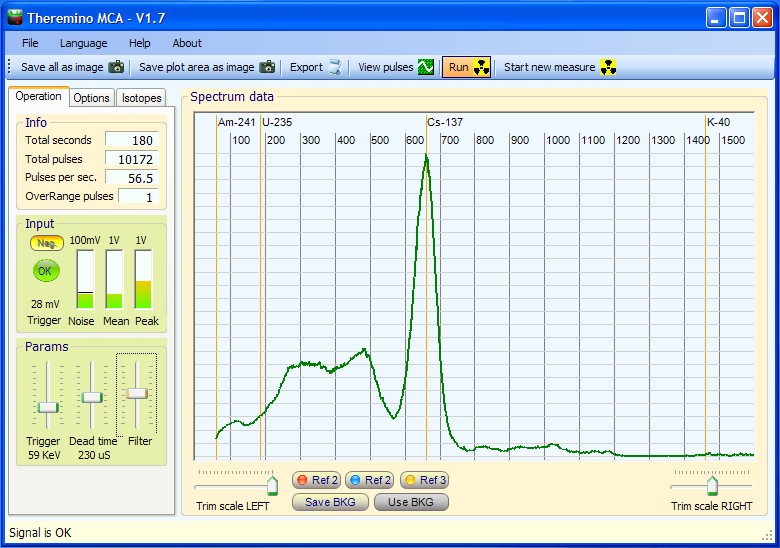
Effettuare un controllo con i marker prima di ogni misura è un sistema rapido, preciso e molto affidabile. Si consiglia di mantenere sempre in posizione due piccoli campioni (ad esempio Cesio e Americio) a distanze opportune, in modo da avere sempre due piccole righe di riferimento. Il Cesio è più debole e lo si tiene abbastanza vicino alla sonda mentre l’Americio lo si tiene a una decina di centimetri, oppure lo si racchiude in una capsula, per diminuire la sua attività e poterlo tenere vicino alla sonda.
Le due righe dovrebbero essere della stessa altezza e abbastanza piccole da non disturbare le misure. Se non si devono misurare proprio il Cesio e l’Americio, allora i due marker possono stare sempre in posizione. Vedere le loro righe sul grafico finale (eventualmente commentate) da la sicurezza che il grafico è perfettamente calibrato.
Costruire un pozzetto in piombo
Da usare per misurare il Livello di Radioattività del fondo naturale e di sostanze debolmente radioattive.
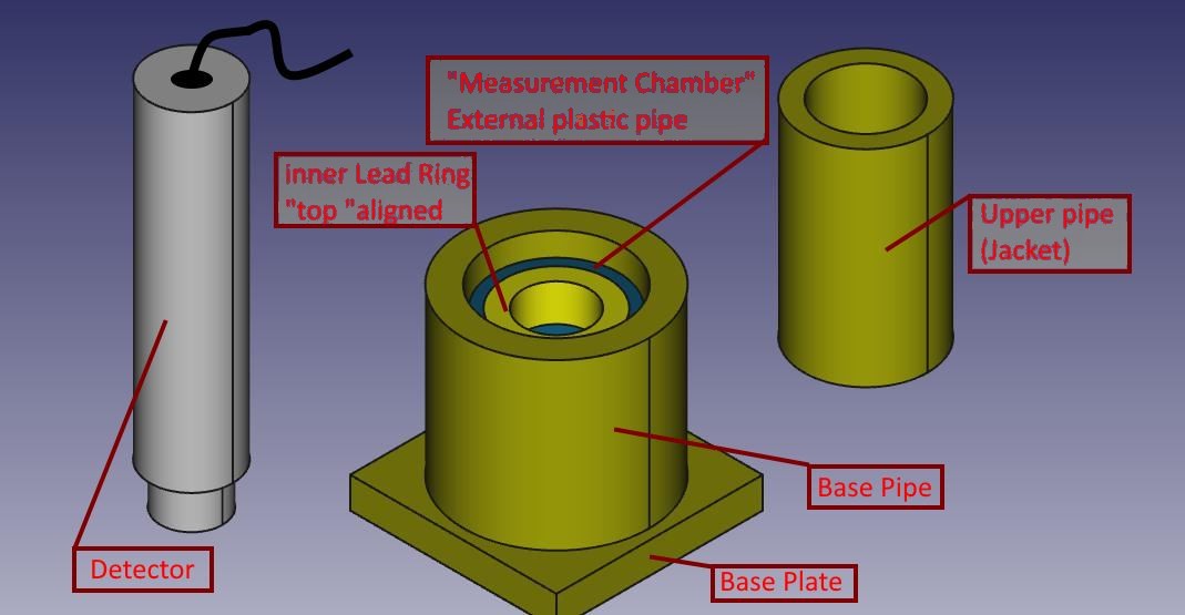
Il pozzetto di misura è costituito da una piastra di base, più alcuni cilindri concentrici, di varie misure e spessori. Tra i componenti si lascia un po’ di lasco, per facilitare l’assemblaggio.
Il materiale color ottone in realtà è il piombo, per distinguerlo dall’alluminio grigio della sonda, mentre il pezzo di cilindro interno (appena visibile) è l’unico di plastica, con anello concentrico e solidale in piombo.
Tutte le parti in piombo sono state realizzate a partire da lamiera da 1,5 mm di spessore, tagliata con una comune forbice da lamierino e sagomata a mano avvolgendola intorno a cilindri di alluminio/acciaio/plastica che avevo a disposizione (utilizzati solo come “dime”).
La piastrina di base è stata realizzata piegando più volte una striscia di lamiera di pari larghezza, ottenendo alla fine un discreto spessore.
La lamiera si piega facilmente attorno al bordo dritto di un tavolo e si appiattisce con colpetti di martello. Il piombo infatti è molto malleabile.
Tutti i pezzi sono stati avvolti con del nastro di carta sufficientemente largo, in modo che maneggiandoli non si viene in contatto diretto con il piombo, che tende sempre a sporcare le mani. Anche per questo è bene calcolare un po’ di lasco tra i vari diametri dei pezzi, in modo poi che il rivestimento di carta non crei problemi all’inserimento/sfilamento dei cilindri stessi, che parzialmente devono entrare uno dentro l’altro (come per il cilindro di base e la camicia superiore)
Per misurare si segue questo schema:
- Si pone innanzitutto su di un tavolo la piastra di base ed il cilindro di base;
- Si inserisce il campioncino da sottoporre a test dentro il tubo di base, in modo che sfiori la parte interna (più bassa) dell’anello della camera di misura: si possono infilare sotto ad esso degli opportuni distanziatori;
- Si mette la camera di misura (cilindro plastica ed anello piombo solidale) in modo che il sottostante campioncino sia centrato sul fondo dell’anello;
- Si infila la camicia superiore all’interno del cilindro di base: essa si appoggerà al tubo di plastica e si manterrà concentrica al foro dell’anello di piombo in modo da permettere il successivo inserimento della sonda;
- Si inserisce la sonda : nel mio caso a incastro nell’anello di piombo della cameretta di misura.
Dalle prove che ho fatto questo setup riduce il rumore di fondo da quasi 20 cps a 3,1 cps
Marco Russiani
Download di questo progetto, completo di ulteriori informazioni e immagini:
![]() Theremino_Pozzetto_di_Misura_ITA.pdf
Theremino_Pozzetto_di_Misura_ITA.pdf
![]() Theremino_G-Ray_Test_Chamber_ENG.pdf
Theremino_G-Ray_Test_Chamber_ENG.pdf
Power supply
——————————————————————————————————
A good PMT power supply must be stabilized, the PMT amplification changes with the supply voltage.
With a not stabilized power supply, every little change in the ambient temperature, shifts the isotope lines making very difficult to do any serious spectrum.
In addition, because Gamma Spectrometry needs long analysis times, if the voltage changes, the rows will be enlarged, and the resolution reduced.
Some producer, like Gamma Spectacular and other kits or projects you can find in Internet, are using not stabilized power supplies but then they say something like this:
“Wait 10 minutes of stabilization before to start”
“Test the calibration with Cesium before and after the analisis,
if the calibration is changed in this time, repeat the analisis.”
they do not say this… but…
“Do not change the room temperature, do not open doors and windows…”
Negative Power supply
——————————————————————————————————
It is better to use a positive power supply, so it will be possible to use the same shielded cable for the signal and for the HiVoltage
This is not only to simplify the connections but mainly to avoid ground currents created from the double wiring ground loops.
With a double wiring it is possible tu use the “normal” power supplies (commercial HV generators) with about 10mV of noise because the switching noise is not applied to the anode.
But with a double wiring you can get a maximum dynamics of about 60dB because dynamics is degraded by HUM and cable noises. (with our single wire solution now we get some 110 dB as you can see in the documentation files of the ThereminoMCA program)
Please read mainly the file “PmtAdapters_ENG.pdf”
Hardware ADC
——————————————————————————————————
There are no hardware ADC with the requested dynamics so all the hardware MCA are using complicate methods (“Sliding Scale”, “Pole zero compensation” and other very hard and expensive methods to get a reasonable number of bins)
The hardware ADC can be very fast (maybe 1Mhz) respect to a audio ADC (192 KHz)
But audio cards are so requested in the past 20 Years that they have achieved incredible performances. The audio card ADC are 16 bit and are internal oversampled so it is normal to get about 110 dB of dynamics (about 40 dB more than a normal 10 ADC with a fraction of its cost)
Signal conditioning circuit
——————————————————————————————————
Either using a hardware ADC or a soundcard ADC the signal must be enlarged because the PMT times are about 100 to 300 nS (3 MHz to 10 Mhz)
If the PMT pulses are not enlarged the ADC aliasing produces a strong degradation of the overall system resolution. (isotope rows are enlarged)
A good signal conditioning circuit must produce a well balanced and slew limited signal.
Please read the file “PmtAdapters_ENG.pdf”
bye
Livio
C’è un limite al numero di impulsi al secondo leggibili da una “Sound Card”?
Per evitare problemi di pile-up si potrebbe allontanare la sorgente o interporre schermi non metallici?
Quanti sono i canali utilizzabili?
Grazie delle interessanti domande, sono una buona occasione per parlare di questi aspetti.
LIMITE DI IMPULSI PER SECONDO
Il limite di impulsi per secondo non è assolutamente un problema per tutte le normali analisi da laboratorio.
Gli impulsi per secondo sono sempre troppo pochi.
Usando una (buona) scheda audio, come quelle USB da noi consigliate, il sampling rate è 192 KHz e il limite di impulsi per secondo circa 5000
SCHEDE AUDIO E CONDIZIONAMENTO DEL SEGNALE
E’ bene non usare le schede audio presenti sulle motherboard dei PC perché non sono modificabili. Usando schede USB invece, il condizionamento del segnale (limitazione dello slew-rate e zero-pole-cancellation) viene da noi completato nella scheda audio stessa, con un passa alto a 6 dB/ottava che riduce il rumore a bassa frequenza e produce un impulso finale di forma perfettamente “bipolare”. Ulteriore modifica alle nostre schede audio e’ l’alimentazione lungo lo stesso cavo di segnale in modo da evitare i ground-loops (anelli di masse prodotti da cablaggi con doppio cavo per alimentazione e segnale)
RAPPORTO SEGNALE RUMORE
Tramite l’uso di ADC a 16 bit e over-sampling le schede audio riescono a dare fino a 110 dB di rapporto segnale/rumore (almeno 40 dB oltre i miseri 60 dB ottenibili dagli ADC a 10 bit degli MCA hardware)
Gli ADC delle schede audio, in unione con l’alimentatore a bassissimo rumore da noi studiato e con il nostro circuito di condizionamento del segnale, riescono a produrre un incredibile rumore finale di soli 70 uV eff (micro volt non millivolt!)
INTERPORRE SCHERMI METALLICI
Se ci si trovasse ad analizzare un pezzetto di reattore nucleare esploso (cosa che non consiglierei a nessuno) basterebbe allontanarlo un po’. Interporre schermi non è una buona idea perché tutti i materiali schermanti hanno attenuazioni dipendenti dalla energia e possono produrre raggi X che alzano il tappeto di rumore in alcune zone del grafico.
Allontanare il campione produce invece una attenuazione costante a tutte le energie (stiamo parlando di raggi gamma), attenuazione che cresce con il quadrato della distanza ed è facilmente regolabile.
CANALI UTILIZZABILI
L’applicazione Theremino MCA ha un regolatore del numero di canali a sei posizioni e un limite a 4096 canali. Si potrebbe facilmente aumentare il limite massimo ma fino ad ora nessuno lo ha ritenuto utile (aumentare troppo il numero di canali riduce la velocità di riempimento degli stessi)
Il limite dato dall’ADC e dal rapporto segnale rumore, è invece oltre i 60 000 canali (e qui si vede la vera differenza tra il nostro approccio e quello degli MCA hardware del secolo scorso)
I want to say A GREAT BIG THANKS for the English translation on the latest Theremino software. I know it must have taken many additional hours of work to complete, and want the Theremino Team to know how much we appreciate it.
Please keep up your wonderful work on this truly amazing software! Your team is very much appreciated!
Tom Hall / iRad, Inc.
Hi. Great project. I have one question. On the schematic DZ1 is MMSZ5270 this is 91V zener diode.
We need there 9.1 or 10V zener. Please correct me if I am wrong.
Thanks
Yes it is true, the MMSZ5270 is a SMD 91 Volt Zener, but it must be a 9 to 10 Volt zener.
Normally we use a 1N757A.
Version 3.3 of the schematics and building plans is here: https://www.theremino.com/technical/schematics
Thanks for your observation.
bye
Livio
The PmtAdapter Version 3.3, with all the last improvements is published here:
https://www.theremino.com/en/technical/schematics/
The images are detailed and can be enlarged with the left mouse button or downloaded with the right mouse button.
Greetings from Australia and many thanks to the Teremino team for your remarkable work in hardware and software and to share your inspiring results so generously open source!
While I am waiting for the Geiger Adaptor, master and tubes to arrive I am now also considering the MCA and did some costing of the probe.
The best price I could find for an enclosed NaI cystal 1 ½” x 1 ½” has been roughly $ 230 including shipping (Sinoma, China via Alibaba) with a 2×2” about” about $ 320 to the door.
Using the same Phillips Photonis PMT XP5312/SN as in DIY Physics Paint Can scintillation probe project
http://www.diyphysics.com/2013/01/12/a-low-cost-super-sensitive-paint-can-scintillation-probe-for-the-prutchi-cdv700-pro/
and mentioning this project when ordering from the supplier Sphere
http://www.sphere.bc.ca/test/photo-tubes.html
the tube can be bought for a reasonable $ 49 plus shipping
.
In the Paint Can Probe project they only use a Bicron plastic scintillation crystal, which generally claimed is not suitable for gamma spectrometry.
However, googling this I found that new doped plastic scintillation materials have been developed with much improved properties suitable for spectrometry but I could not find a supplier, only scientific papers. There are also papers describing calibration and correction methods for plastic scintillation materials to make them useable in spectrometry.
Could these methods be employed with the MCA making possible the use of an inexpensive scintillation probe using a plastic crystal?
Does anyone know a supplier or has more details for the improved plastic scintillation materials?
Will there be assembled PMT and audio cards available? Thank you and
Kind regards
Eckhard
Hi,
we are very interested to make inexpensive scintillation probes using plastic crystals or maybe some liquid that can be painted on the sides of a Paint Can.
Calibrations and corrections are not a problem, our software can do any required operation and we can easy add new corrections.
The problem is the resolution of the scintillator material, we tested a BICRON BC408 (1 x 1 x 1.5 inch) (10 Euro) with a FWHM of about 60% at 660 KeV – Maybe the version 4 of our software can increase a little this resolution but not down 40% or 30%.
The BGO we are using is not expensive and (with our version 4 resolution compensator) has a resolution of about 10% or a little better (but the Radium rows are not well resolved)
We searched for long time, other good scintillator materials without any result.
————————–
Please consider also that the “Paint Can” Probe project is not so sensitive as they claimed (with the Hamamatsu PMT and a little BGO we get about 25 times more CPS)
I do not know why but I suspect that the scintillator they use is not so good.
bye
Livio
========================================================================
Alcuni utenti non riescono a ridurre il rumore del PmtAdapter, copio qui alcuni brani
su questo argomento, tratti da varie mail.
I consigli sono in inglese – gli italiani possono fare TASTO-DESTRO -traduci in italiano.
========================================================================
Version numbers and Current Limiter
———————————————————————————————
The Audio Card has not a version numbers but in the last weeks we added the “limiter”
Test always if the jack is completely plugged
Without the limiter – if the jack is not completely plugged –
the inductance in the Audio Adapter can MELT !!!!
When Alessio has finished the limiter PCB it will be possible to send to you a “limiter”
please call to Alessio for this.
If you prefer I can install it for you or you can see here how to make it here:
hardware/outputs/actuators (the SMD version at the end of the page)
The limiter substitutes the inductor in the audio card also with better results (less noise)
Capacitor in the Pmt Adapter
———————————————————————————————
For some user the noise way is: L1 – L2 – R14 —> OUT
– C13 and C14 must be LOW-ESR (max 0.03 ohm series)
– L2 must be 1mH (max 2 ohm series)
The LOW ESR capacitors are very important !!!
– normal capacitors are 1.5 ohm series resistance
– low esr are 0.03 ohm
The difference in noise reduction is 50 times.
And it is very easy to mount wrong capacitors
because the text “LOW-ESR” is not present on the capacitor body
Capacitor in the Audio Card
———————————————————————————————
Also the capacitor in the audio card must be LOW ESR (220uF or 330uF)
In the first PmtAdapters this capacitor was not OK
Sorry for this !
We are not professional producers, we are a “Non Profit Organisation”
Alessio was making some kits for the friends but never thinked to make so many
kits in so little time !!! And all the people was pressing to get immediately the kit…
I can personally send to you some euro, to compensate for this errors, if you send
to me a PayPal button – or you can considerate this a donation to our organization.
Jack with instable connections
———————————————————————————————
We found some audio card with the jack plug not OK
Try to rotate the jack to see if the noise changes
If the noise changes then the jack plug GND contact is not pressing OK on the jack
Open the card and bend a little the three plug contact to make them more solid
USB connections and/or USB noises
———————————————————————————————
Sometimes also the USB plug of the computer contacts are not completely clean.
Try to move slightly also the USB
Try also to use another USB port
(every time restoring the AGC = OFF and the minimum mixer volume)
Try also on another PC to verify if the noise comes from the USB
(some PC has a USB producing a great switching noise)
bye
Livio
========================================================================
Alcuni utenti che si procurano i componenti da soli hanno trovato difficile reperire:
– lo Zener 1N757 da 9 Volt (questa sigla era anche sbagliata negli schemi)
– il Mosfet BSP 300
Copio qui alcuni brani su questo argomento, tratti da varie mail.
I consigli sono in inglese – gli italiani possono fare TASTO-DESTRO -traduci in italiano.
========================================================================
Zener
—————————————————————————————————————–
The zener is now corrected with the 1N757A
The 1N5239 is not a good equivalent, it has a too high leakage courrent
1N5239 = 3 uA1N757 = 0.1 uA
Mosfet
—————————————————————————————————————–
Someone has proposed the STN1NK80Z but I think it can not work
(or work with a low effciency, more current consumption,
and only if the max output voltage is limitad to 800. 1000 Volt)
Drain courrent with gate-source voltage = 4.5 Volt
STN1NK80Z = 10 mA
BSP300 = 200 mA
The first four sellers can send to you the BSP300
the number of pcs is the quantity actually present in the wharehouse
Alessio ... BSP300 ........... 5 pcsFarnell ... 1471698 .......... 10666 pcs
Distrelec . 610259 ........... 183 pcs
RS ........ 752-8211 ......... 45 pcs
DigiKey ... BSP300 E6327-ND .. (actually in backorder)
Mouser .... 726-BSP300L6327 .. (sometimes it has cutted Tapes)
In Poland inter-chip.pl has BSP300. (i dont know how many polish guys are interested in this project :))
Only parts i could not get are C5 and C6. I used MKS4-47N/1500VDC poliester capacitors to filter output. (i dont know how much this affect quality of output voltage??).
My PmtAdapter is working. Few things left: aluminium box, shield. sound card mod.
When I finish i will Donate theremino :) You are awesome !
Dear Martin,
your MKS4-47N/1500VDC are only more large and more expensive, but electrically they will work absolutely OK
Another possibility is to use 2 x five 10nF/2000V ceramic disk capacitors that can be easy find on eBay (making 20 holes on the PCB with the Dremel)
Please make also, great attention to use 1000uF LOW ESR capacitors with not more than 0.03 ohm series resistance ! And 220uF LOW ESR in the Audio Card.
It is difficult to reduce the noise, although a good spectrometry can be done with 2 mV and more, we need better. We are not like a normal “iPod to Audio Card” user, we are very picky and we want a 200uV pep noise !!!
Volevo ringraziare il Theremino team per l’eccelente lavoro svolto.
Ho recentemente ricevuto il Theremino adapter, ottenendo notevoli risultati su tutti i fronti.
Devo dire che inizialmente ero un po’ scettico riguardo al sistema di calibrazione: avevo provato una delle versioni “2” del programma, con il Gamma Spectacular, ma il risultato non mi aveva entusiasmato.
Tutt’ altro discorso adesso, con il Theremino adapter e la versione 4.6 del programma: eccellenti risultati e calibrazione precisa e stabile nel tempo. Davvero un eccelente sistema di spettromentria ad una frazione del costo necessario per ottenere simili risultati con i metodi finora normalmente usati. Notevole anche la massa di informazioni che avete fornito nella cartella Docs, molto utili a chi, come il sottoscritto, non e’ certo un “electronic wizard”.
Per finire un grande “Grazie” ad Alessio per la gentilezza, rapidita’ e generosita’ con cui ha risolto un problema causato dalla mia imperizia.
Proseguite cosi’ e cordiali saluti a tutti voi !
Luigi
Vedo che siete arrivati alla versione 3.3
Io ho la versione 3.1
Qual’è la differenza di prestazioni fra le due?
Noto dallo schema che la 3.3 monta sia il transistor che il mosfet
Si possono montare tutti e due o, uno o l’altro a scelta
Io sono soddisfatto del mio Theremino ma se con questa versione posso ottenere dei miglioramenti
posso provvedere all’upgrade
Fiorenzo
La versione 3.3 ha solo piccole differenze sullo stampato:
– la resistenza da 2.2 ohm sul lato saldature
– un ponticello per selezionare il modo HF (da non usare se tutto va bene come nel tuo caso)
– la serigrafia fatta meglio
Come prestazioni non cambia nulla
E anche il transistor non è meglio del Mosfet.
Il transistor serve come alternativa per chi non riesce a trovare il Mosfet ma non da nessun vantaggio, anzi consuma un 10 mA aggiuntivi.
Livio
Theremino MCA version 4.5 was used to test this sample of black fungus like material, that came from Japan. This resin encapsulated sample has reportedly come from somewhere in the Minamisoma area Japan. A contact in Japan sent this sample to a friend. This is my test chart of it.
http://sccc.org.au/wp-content/uploads/2013/04/Minamisoma-Cesium-290313-TV45-23c-25040-MB.jpg
This fungus started growing on the concrete, and rock surfaces in lots of places in Japan, after the Fukushima Nuclear disaster. It appears to be bio-accumulating Cesium.
Scintillators are less sensitive as you go to higher energy keV. The Theremino MCA software allows you to increase the magnification of the higher energy peaks. The peaks in this Theremino MCA V4.5 software chart have been energy compensated, to bring out the smaller details at higher energies. The sample very small, grams or less.
A professional lab reported test results 117 Bg Cs-137 and 58 Bq Cs-134.
I don’t know the exact weight. Spectrometising is trying to find out.
Any comments or suggestions, regarding the results of this test chart results are welcome.
There is no copyright placed on the chart screen shot, so you can copy it, and make use of it where ever you like.
This is a very detailed and interesting image!
Thanks for your reasearch and, please, send to us any news.
We published your image here:
https://www.theremino.com/blog/gamma-spectrometry/images
bye
Livio
This black fungus material sample from Japan, contaminated with Cesium Cs-137 & Cs-134, is encapsulated in resin for safety reasons. So we don’t know how much it weighs. We are trying to find out. It may not have been weighed when it was collected. Visually, looking at the encased sample, it would be a few grams if that.
Here is a pen tip placed next to the sample, to give you and idea how small the sample is. The black center is the sample. Also, the sample does not fill up the small sample container, that is in the center of the resin encasement. The sample container is only around two thirds full.
http://sccc.org.au/wp-content/uploads/2013/04/Japanese-black-fungus-material-sample-with-pen-tip.jpg
Hi. What size of crystal (NaI(Tl)) was used ?
Are there any plans to run Forum here on theremino site? i done my pmtadapter and detector (now fine tuning) and it would be great to share expierience with others that use PmtAdapter and theremino MCA. (i know yahoo groups and fusor.net)
Martin S.
“What size of crystal (NaI(Tl)) was used ? ”
Voltage Setting:
800 Volts, tried 850 but put it back to 800.
Scintillator:
Alpha Spectra NaI, Model 818/2B, resolution 7%
Scintillator:
2″ x 2″ Alpha Spectra NaI, Model 818/2B, resolution 7%
Suggestion,
It would be great to have a Theremino MCA program feature like the FWHM for Bequerel calculation. After the efficency of your scintillator is worked out, and entered in the settings, the software could be used to calculate the becquels amount for a highlighted peak area.
Bequerel is the number of decays per second and it is not possible to measure the decays produced by a sample.
It is not only matter of efficiency but also of geometric parameters, of distance from sample to scintillator, wall material, sample emitting area, scintillator capture area, and many other factors.
If some of those parameters is changed, for example the distance by some mm, the measured value can change by 100% or more.
With our sensors (scintillators and PMT) it is not possible to intercept all the decays or compensate with a “correction parameter”
With our sensors are possible only relative measures.
So we prefer do not increase the erroneous idea that Bequerel and Curie values can be “measured” without a complete specification of those parameters.
We know that other software, and also Geiger counters like GammaScout, are doing this but it is not correct.
“It is not only matter of efficiency but also of geometric parameters, of distance from sample to scintillator, wall material, sample emitting area, scintillator capture area, and many other factors.”
Agreed
Even scintillator efficiency varies from low to high keV.
Still, would be nice to know the number of counts in a given peak area. PRA allows you to highlight a peak area, and then it totals the counts for that highlighted peak area.
Yes, the “area total counts” and maybe also the “area counts per second” are useful indications.
Thanks for the help, we may include it in the next versions, maybe with the names “Total” and “CPS”, if you agree.
In the meantime you can do a left click on the graph, and read the counts for each bin in the status bar. With some experience it is not difficult to estimate also the counts for the other parts of the graph.
“Yes, the “area total counts” and maybe also the “area counts per second” are useful indications.”
Yes, I think that it would be a positive additional feature to an already great program.
Here are two charts of a 100 grams of pure Potassium Chloride. The charts were recorded in Theremino MCA V3.8 and V4.5, for comparison purposes.
The chart recorded with Theremino MCA V4.5 has a lot better FWHM, and is showing more detail than the V3.8 chart.
http://sccc.org.au/wp-content/uploads/2013/05/Potassium-Cholide-100-grams-010513-TV38-22c-855546-texts.jpg
http://sccc.org.au/wp-content/uploads/2013/05/Potassium-Cholide-100-grams-010513-TV45-22c-89647-texts.jpg
Thanks, very good resolution and perfect settings! It is very difficult to see the Potassium Chloride and there are very few images about it. It is so difficult that someone says that ThereminoMCA not works at so high energies.
Sorry that the images were taken in full screen and then reduced to 800 pixels, so the writing are difficult to read. It would be better to keep ThereminoMCA non-fullscreen.
Here are the original full size screen shots. I resized the images in the above post, because on another forum you could not see the all the image on the screen.
http://sccc.org.au/wp-content/uploads/2013/05/Potassium-Cholide-100-grams-010513-TV38-22c-855546-text.png
http://sccc.org.au/wp-content/uploads/2013/05/Potassium-Cholide-100-grams-010513-TV45-22c-89647-text.png
Yes thanks.
So I have not explained well the problem…
Now I try to explain it better.
If the ThereminoMCA is used full-screen or with a large window, the grabbed images will be large (1280 pixels or more)
It is not possible to see so large images on the WEB, on the NetBooks and on tablets (and it is very annoying to zoom and pan them continuously)
There are no advantages to use large images and to use ThereminoMCA in full-screen, but only disavantages:
1) The spectrum rows are not better if using large windows but the text becomes proportionally little, and not proportioned with the graph
2) The equalizers can not be docked
3) When the images are reduced to a Web-Friendly 800 pixel the text will be poor and diffcult to read
4) When the images are reduced all the image becomes de-focused
The good solution is to work always with ThereminoMCA in a window, with width about 800 or 900 pixel.
In breve,dispongo di un rivelatore a scintillazione SPP-2-NF funzionante e obsoleto….
può servire per prove con MCA o altri degli ottimi programmi che rendete disponibili ? Il campione di Cs137 di corredo indica 256 C/S, mentre lo strumento ne legge 150,penso dipenda dal naturale decadimento,il che la dice lunga sull’età del tutto… non so se questa è la sede giusta per queste info,nel caso indicatemi il modo corretto per farlo,sto aspettando l’arrivo dei circuiti Theremino Geiger ,tanto per rimanere in argomento!? Complimenti davvero per il livello di qualità dei circuiti e delle spiegazioni,grazie per il tempo che ho preso, saluti cordiali, Claudio
Gli ho dato una occhiata e sembra contenere un tubo fotomoltiplicatore e un cristallo Nai(Tl) – questi sono gli unici due componenti utili. Direi che usati potrebbero valere intorno ai 150 euro (sempre che funzionino bene e che si riesca a modificarli per la spettrometria)
Di base loro parlano di 30keV quindi cosi’ com’e’ e’ molto rumoroso per la spettrometria. Per farlo funzionare bene lo zoccolo del PMT andrebbe ricablato come indicato nelle istruzioni del nostro PmtAdapter. Poi dovresti fare o comprare in kit un PmtAdapter, scrivi ad Alessio per indicazioni precise sui prezzi: alessio.giusti@meteolink.it
Se invece vuoi usarlo cosi’ come’e’ potresti tentare di mandare l’audio out di cui dispone verso la scheda audio e contare gli impulsi con theremino AudioIn e ThereminoGeiger, oppure vedere se i suoi impulsi sono adatti anche per la spettrometria con il software ThereminoMCA. Usandolo cosi’ le caratteristiche saranno scarsine ma non spendi niente e non devi modificarlo.
Ciao
Livio
Is this proof, that some of the Beryllium Be-7 in our rain tests here in Australia, is from Fukushima?
For background on this subject, please read this article on using Beyllium Be-7 as a tracer for I-129.
http://www.sciencecodex.com/dartmouth_scientists_track_radioactive_iodine_from_japan_nuclear_reactor_meltdown-89004
————————————————————
* Be-7 is produced by cosmic ray spallation in the upper atmosphere. It takes around two weeks to reach sea level. My understanding is that the Japanese have been pumping large amounts of liquid Nitrogen onto the multiple molten coriums at the Fukushima Nuclear disaster, to cool them down. The neutron bombardment, plus lots of underground corium venting, has also been releasing large amounts Beryllium Be-7 and 1-129.
True or False?
————————————————————
There is a natural Beryllium Be-7 and Lead Pb-210 cycle here in the Southern Hemisphere. There is a more Beryllium Be-7 and Lead Pb-210, detected in rain washouts, during summer than in winter. There appears to be above averag detected Beryllium Be-7, in this test for May 2013. The Sun had been relatively quite during May 2013.
So the question.
Is some the detected Be-7 being detected here in Australia from Fukushima? If there is a significant presence of I-129 and U-235 in the rain here, it suggests that it is. That the Be-7 has travelled here from the Fukushima Nuclear Disaster.
This is open for discussion, I am interested in constructive feedback, and alternative views on the test results.
Looks like a detection of Iodine I-129 from the tin roof down pipe polyester filter. It was collecting rain off a 36 sqm tin roof at my location.
Test chart using Theremino MCA V4.5 software.
http://sccc.org.au/wp-content/uploads/2013/06/Down-pipe-polyester-filter-020613-TV45-20c-88395-+-text.jpg
If it is, it is still a very small detection of I-129, because the filter was in place for all of May. Mind you, not all of it would have been captured using this filter system. Lots of Beryllium Be-7 is also present! If this is present in the Southern Hemisphere, it would suggest that there is a lot more in the rain in the Northern Hemisphere!
Nimbin Australia has been getting huge Radon washouts this year. The rain swab test charts from that location have been showing lots of Lead Pd-210 and Beryllium Be-7. Lead Pb-210 is the end isotope of the Radon daughter decay chain.
Nimbin test chart using Theremino MCA V3.8 software
http://sccc.org.au/wp-content/uploads/2013/06/East-Coast-Northern-New-South-Walles-rain-swabs-96-+-69-test-070213-TV38-Be.png
Theory
Because the I-129 at 39.6 keV, and Pb-210 at 46.5 keV, have energy peaks so close together it can be difficult to tell them apart with a NAI scintillator. If they are present at the same time, the peak that shows will drift toward the 39.6 kev if more I-129 is present, and towards 46.5 keV if more Pb-210 is present.
The experimental Theremino MCA V4.5 software used in this test, is a bit noisy near background. It is a lot more sensitive than the other scintillator MCA software I use. It is just that the noise at low CPS activity can make it harder to interpret isotope peaks.
Beryllium Be-7 has a theoretical back scatter peak at around 166 keV, very close to the 185 kev for Uranium U-235. There is the possibility that it is contributing to the size of the peak at that the U-235 location. It may also explain the width, and rounding of that peak at around 185 keV.
Disclaimer: I am an amateur. Human error can provide incorrect information, and equipment malfunction can produce false readings. Do not rely on, or take action upon information presented here, without further research.
Ho installato Theremino MCA e collegato il modulo PMTAdapter fornitomi da Alessio. Il tutto ha funzionato immediatamente ed una volta impostati i corretti valori di energia forniti dalla mia sonda, si è generato un grafico di ottima qualità usando le classiche sorgenti Am241 e Cs137. Non ho avuto necessità di leggere il manuale, cosa che in realtà sto facendo ora per approfondire alcune regolazioni. Avevo dei dubbi sulla mia sonda realizzata inserendo in una Ram63/3 un NaI(Ti) da 1,5″ x 1″ sul vecchio PMT abbinato in origine allo scintillatore plastico, ma la resa appare ottima per sensibilità (6000 cpm per il fondo) e seletività.
Complimenti ad Alessio e Livio e collaboratori.
Una domanda. Con XP per settare il volume di ingresso va bene un clic di mouse partendo da zero, in modo da rendere ripetibile la misura. Con Windows 7 il primo clic restituisce in una finestrella il valore numerico 20 a cui corrisponde un valore di rumore medio di circa 0,7 KeV con la linea verde appena sopra la linea di base rossa. Ma il valore è impostabile numericamente sulla finestrella, per cui ho provato il valore 8 e mi da un rumore medio oscillante tra +0,2KeV e -0,1KeV. Decisamente più basso dunque. La domanda è la seguente: il fatto che con questa regolazione la linea degli impulsi verde sia sovrapposta alla linea rossa ed invada lievemente il campo dei valori negativi può comportare qualche inconveniente a livello di funzionalità software?
Con tutti i sistemi operativi si deve sempre impostare la posizione di minimo guadagno ancora funzionante. Con XP questa posizione non è proprio con il cursore a zero perché altrimenti l’ingresso si spegne. Con Windows7 e 8 si deve portare il cursore proprio a zero o mettere il valore numerico al minimo possibile.
In questo modo si diminuisce al massimo il guadagno dell’ingresso audio e si minimizza il rumore di fondo dell’ADC della scheda audio.
Ridurre la amplificazione al minimo permette anche di inviare all’ingresso segnali elettrici intorno al volt picco-picco senza che questi vengano tosati dai limiti minimo e massimo dell’ADC.
Il risultato finale è di massimizzare il rapporto tra segnale e rumore (segnale massimo prima del clipping diviso rumore dell’ADC + rumore sui cavi + rumore dell’alimentatore)
La riduzione di guadagno viene poi facilmente compensata aumentando leggermente la tensione sul tubo PMT
A questo proposito ricordo ancora a tutti che si deve tenere il cursore di regolazione, che si trova a destra in basso della finestra principale, approssimativamente a metà della sua corsa, e regolare la tensione sul tubo PMT per poterlo tenere così. Altrimenti si rischia di non sfruttare tutta la dinamica possibile oppure di tosare gli impulsi di alta energia.
La posizione della linea verde
———————————————————————————————–
Tutte le schede audio, alcune di più altre di meno, hanno la linea di zero leggermente alta o bassa. Cambiare regolazione dei cursori di input sposta notevolmente questa posizione per cui si devono posizionare questi cursori stabilmente al minimo e non muoverli più.
Poi si compensa la posizione della riga verde con “Audio zero trim”
– Sconnettendo il BNC che va al PMT
– Disabilitando il base Line Test
– Impostando MinEnergy = 0 nel PulseShape Visualizer per poter vedere il rumore di base
– Oppure usando “Tools NoiseTest” che lo fa in automatico
Senza Baseline Test
———————————————————————————————–
Se la riga verde è troppo alta si ottiene del rumore alle energie basse, invece se è bassa le righe si spostano a sinistra e gli impulsi di bassissime energie scompaiono sotto allo zero.
Con il Baseline Test attivato
———————————————————————————————–
La posizione della riga verde non conta più niente perché viene ricalcolata ad ogni imulso (ma è bene lo stesso averla approssimativamente a zero per poter usare bene il Pulse Shape Visualizer)
In tutti i casi
———————————————————————————————–
Se la linea verde è leggermente sopra o sotto alla linea rossa non si ottengono cambiamenti significativi nel funzionamento. Con “leggermente” si intende qualche centinaio di uV.
Grazie di aver condiviso queste interessanti domande sul blog.
ciao
Livio
Grazie Livio per le dettagliate istruzioni.
Ma a questo punto sorge una questione. La mia sonda (con il classico partitore 13 resistenze da 10MΩ ed una da 1ΜΩ) accetta di essere alimentata con 1300V al massimo. Ulteriori incrementi non spostano il grafico verso destra, ovvero le energie non aumentano. Se imposto il volume audio al 5%, cursore in basso a destra al centro e equalizzatore disabilitato, il picco dell’Am si piazza a 25-30 KeV e il Cs a 250 KeV. Impostando il volume con un click (20%), l’Am restituisce 50 KeV ed il Cs 490 KeV.
Per risolvere il problema posso:
1. lasciare il volume al 5%, fare tutta la misura ed alla fine stirare il grafico verso destra fino a far coincidere le energie con i valori caratteristici.
2. aumentare il volume al 20% ed ottimizzare le energie con l’equalizzatore ed il cursore in basso a destra.
3. ricablare la sonda con resistenze (quale valore?) che mi restituiscano impulsi più energetici.
Qualche suggerimento? Grazie
Non saprei dirti come ricablare la sonda per avere più segnale, non credo che sia possibile.
Probabilmente il tuo PMT ha un guadagno piuttosto basso rispetto all’Hamamatsu cui sono abituato, mi spiace ma non ho mai provato una Ram63.
Direi che dovrai lavorare con il mixer al 2o o al 25% e accettare di avere qualcosa da 0.5 a 0.9 mV di rumore… se stai sotto al millivolt comunque è sempre un rumore bassissimo e probabilmente con la Ram63 non si può fare di meglio.
La versione 5.0 appena pubblicata non si fa più ingannare dal rumore e dal ringing che precedono gli impulsi e quindi un minimo di rumore non ti impedirà lo stesso di vedere energie estremamente basse, anche sotto ai 5 keV e, in alcuni casi fino a un incredibile 2 keV. https://www.theremino.com/downloads/radioactivity
Comunque dovrai trovare tu la combinazione di parametri più adeguata per i migliori risultati con il tuo hardware, facci poi sapere come ti sarai stabilizzato… grazie, ciao, Livio.
Grazie Livio. Sotto 1 mV rimango comunque. Vi aggiornerò
Risolto! Era un problema di accoppiamento ottico tra PMT e cristallo. Ho rimesso il grasso siliconico ex novo e le energie sono d’incanto raddoppiate. Probabilmente una bolla d’aria tra le superfici. Con un piccolo ritocco del cursore destro il Cs è centrato.
Ottimo, quindi se ho capito bene hai il cursore al minimo (al minimo segna 5% ?) e hai la tensione inferiore a 1300 Volt ? Sono un po’ noioso a chiederti tutti i particolari ma lo faccio per altri che potrebbero avere una Ram63 e trovare utili le tue misure.
Dimenticavo, l’incremento di segnale ha sicuramente un buon effetto sulla risoluzione, quanto è larga la riga del cesio in FWHM? E magari ci fa piacere se scrivi anche il tipo di cristallo, forse lo hai già scritto o forse è sottointeso dato che hai una Ram63. Probabilmente è un Nai(Tl) ma ho letto che qualcuno lo ha sostituito…
Ho installato Theremino MCA su XP e su Mac con Windows 7, quindi posso variare il segnale di ingresso con libertà. Fra una decina di giorni saprò risponderti con più precisione in quanto sarò in ferie ed avrò più tempo per effettuare prove.
In linea di massima il valore FWHM varia con le regolazioni dell’equalizzatore tra 6% e 11%. Per poter avere un valore abbastanza preciso, lo misurerò senza equalizzatore e con diversi valori di ingresso audio.
Il cristallo è un NaI(Tl) da 1,5″X1″. Ho scelto queste misure in quanto il suo involucro esterno corrisponde alle dimensione del cristallo plastico originale ed ho potuto quindi inserirlo nella sonda RAM senza modifiche meccaniche.
Hi Livio,
I made few tests with two scintillation detectors with ver5.0 and my conclusion is that Theremino is finally superb MCA software. Details and lower energies are now much better with better resolution. Data acquisition is the fastest as it ever have.
With no changes for both (different) probes result is great and with little fine tunning I get superb results and all that after few minutes of tunning. Sure I need to get all voltages tunned and then will be finall results but this is also very good.
PRA had better results in lower energies below som 30 or 40 keV compared to older versions of Theremino MCA and now Theremino from v5 have much better.
Congratulation for great improvment!
Tomy 9A5TOM
PS: As soon as I get few days off off my job I’ll make those new video on my YT channel. Now I can say that it was good that I wait for v5 ;)
Report is ready if you interested into let me know. I published it on GammaSpectrometry group.
A great test, and a great help for us, thanks.
The Ra-226 spectrum is very detailed and the Cs-137 row is narrow, what is the FWHM?
This is the link to the GammaSpectrometry group message:
http://tech.groups.yahoo.com/group/GammaSpectrometry/message/13021
Hi Livio,
Resolution (FWHM) for 662keV for Cs-137 is 7.1%
I get few comments about issue in background substraction.
Please see message thread. I don’t know what kind of algorithm you are using but it is maybe little bit too rigorous. I made calculations in MS Excel (2013) so please read this message:
http://tech.dir.groups.yahoo.com/group/GammaSpectrometry/message/13031
Read notice, it’s not 100% accurate but as a reference is good.
If I can help somehow in that part please let me know.
Kind Regards,
Tomy
The subtraction is only a simple subtraction x=a-b, sorry but I can not figure why it can not work at the best. You can try to discover this.
I sending you mail with formula and explanation.
El programa nos resulta muy útil y práctico, pero tenemos problemas para realizar cálculos en los espectros. Contamos con un detector de radiación Gamma Spectacular GS-1100A, los espectros registrados por éste programa son buenos y fáciles de interpreta, pero requerimos cálculos sobre esos espectros, como determinación de ROI, centroide del fotopico y FWHM entre otros, para determinar la actividad del isotopo asociada a su espectro.
Agradeceríamos información sobre el tema.
Sería de mucha utilidad conocer a más personas en latinoamerica que cuenten con sistemas similares en Espectrometría Gamma.
Saludos cordiales.
Dante Rios
Físico
Lima, Perú
contacto: danrisa@hotmail.com
El valor de FWHM y el centro de gravedad se obtiene pulsando el ratón hacia la izquierda o la derecha en el pico de su interés. (Con los dos botones que obtiene un centrado automático o manual)
El valor de FWHM se muestra en la ventana principal y el centro de la línea de estado inferior.
También se pueden guardar los datos y tratarlos con un programa externo.
También hay nuevas versiones de ThereminoMCA con nuevas opciones en evidencia en esta página: http://pico.dreamhosters.com/ThereminoMcaEn.html
(Este enlace también está disponible en la página de descarga de ThereminoMCA)
saludos
Livio
Detection of radioactive Iodine I-129 in roof gutter moss Australia.
I used Theremino V5 for the tests discussed in this report, so I thought you may be interested in the charted test results.
I recently collected 82 grams of moss that had been growing in roof gutter here, and tested it. It was very wet here for the first half of 2013. August has had no rain, so the moss sample was dry.
I am located here on the east coast of Australia.
http://sccc.org.au/monitoring/Australian-Map.jpg
Moss growing in roof gutter
http://sccc.org.au/wp-content/uploads/2013/09/Moss-growing-in-roof-gutter.jpg
Moss in Marinelli beaker for testing
http://sccc.org.au/wp-content/uploads/2013/09/Roof-gutter-moss-82-gams-in-marinelli-beaker.jpg
Test chart of moss sample using experimental Theremino MCA version 5.
http://sccc.org.au/wp-content/uploads/2013/09/Moss-from-roof-gutter-80-grams-260813-TV5-19c-80781-+-text.jpg
If my assessment is correct, this Southern Hemisphere detection is not a good sign. This is a lot of Iodine I-129. The other possibility is it is Lead Pb-210, or a mixture of both. The main peak is much closer to 40 keV than to 47 keV for lead Pb-210. I have tested this sample with different software, and calibrated a number of times, it very much looks like I-129.
This means it is bio-accumulating. So even though our background levels here have not risen a lot, bio-accumulations could present a more serious issue. The moss also had some other material mixed in with it, that it was growing on, leaves and other organic matter. This test result also suggests that there would be more 1-129 in fallout in the Northern Hemisphere.
I have discussed this test result with some of my contacts here.
Why so much I-129, and not Cesium etc.?
The conclusion is because of its volatility. It can also easily volatilize in an environment, as the temperature increases.
This would allow it to easily spread long distances, like Iodine I-131.
Japanese study of I-129 pre-Fukushima Nuclear disaster.
http://www.ncbi.nlm.nih.gov/pubmed/23829385
Another pre-Fukushima Argentina study, indicates that Norther Hemisphere I-129, can reach the Southern Hemisphere. This study shows I-129 has migrated from nuclear fuel reprocessing plants at Cape de La Hague (France) and Sellafield (UK).
http://www.sciencedirect.com/science/article/pii/S0048969712006353
For the technically minded – Testing procedures, and Becquerel activity calculations.
Scintillator Model:
Alpha Spectra NaI 818/2B, resolution 7%
Voltage setting; 800 Volts
Efficiency 7% at 662 keV
I used radioactive Americium (Am-241), from a smoke detector in the test chamber, to calibrate the low energy peak position, and also the scintillator efficiency at around 40 keV.
Here is the calibration chart for reference.
http://sccc.org.au/wp-content/uploads/2013/09/Moss-+-Americium-+-text.jpg
Estimate of scintillator efficiency at 40 keV
Smoke detector Am-241 activity = 37,000 cps, from my research approximately 1% of this activity is Gamma.
1% is Gamma = 3700 cps (36% of that 1% is at 60 keV)
37 x 36 = 1332 cps = 100% gamma at 60 kev
1295 / 100 = 13.32 = 1%
693 cps was the actual cps in chamber for this peak region
693 / 13.32 = 52% efficiency at 60 keV
Estimated efficiency at 40 keV is approximately 52%.
I used Japanese BecqMoni MCA software to calculate the activity.
Using 52% efficiency at 40 keV.
net count – background = 80039
80039 / 52 = 1,539 (1%)
1,539 x 100 = 153,900 (100%)
Time of test = 79700 seconds
153900 / 79700 = 1.931 cps
82 grams in weight 1000 / 82 = 12.195
1.931 X 12.195 = 23.5 Bq/kg
This may not be an absolute quantification of the scintillator tube’s efficiency at 40 keV, but we are dealing with moss in a large marinelli beaker here. The efficiency of activity is going to be less than the 52% for the Am-241. So the 23.5 Bq/kg activity estimation is probably conservative.
Disclaimer: This is an amateur volunteer run service. Human error can provide incorrect information, and equipment malfunction can produce false readings. Do not rely on, or take action upon information presented here, without further research.
Ciao Livio,
mi chiamo Emanuele ed è la prima volta che scrivo sul blog. Innanzitutto mi permetto di complimentarmi per la varietà di progetti presenti sul sito ed in particolare per quanto concerne la spettrometria Gamma. Vengo al dunque. Sto costruendo un sistema costituito da una sonda scintillatrice Bicron NaI(Tl), dal Theremino PMT adapter ed dal software MCA e dopo varie valutazione ho optato per il progetto Theremino PMT. Ho quindi fatto costruire il PCB del PMT adapter V3.3 ed ho appena finito di montarne uno che sto collaudando impaziente di collegarlo alla mia sonda.
Mi ritrovo però con un piccolo problema (spero che sia questo il luogo giusto..):
Alimentando il PCB mi trovo una tensione stabile di circa 450Vdc sui pin di uscita verso il PMT , che diventano circa 580Vdc ruotando il potenziometro a fondo corsa in senso orario.
Secondo quanto ho letto sui documenti disponibili sul sito la tensione dovrebbe arrivare almeno a 1000Vdc.
Inoltre leggendo la documentazione mi sembra di capire che l’induttanza da 3.3uH è critica e dovrebbe avere una resistenza inferiore a 3 ohms (la mia è circa 8ohms). Potrebbe essere questo il problema o è l’impedenza del mio multimetro che è bassa?
Qualsiasi commento sarà gradito.
Ringrazio anticipatamente per la risposta.
Emanuele :)
L’induttanza non deve essere da 3.3 micro Henry ma da 3.3 milli Henry, credo che il problema sia questo. Se la metti da 3.3 milli Henry funziona anche se ha la resistenza serie da 8 ohm. Però non funziona se è una induttanza molto piccola e comincia a scaricare internamente a 500 Volt o meno. Deve reggere fino a 800 Volt (che duplicati fanno 1600)
Controlla anche l’integrato deve essere un NXP altrimenti farai fatica ad arrivare a 1500 Volt.
Hai usato i diodi giusti a bassissima capacità? E il mosfet giusto?
Un’altra possibilità è che tu stia misurando con un “multimetro”, non si può fare, devi usare un partitore da almeno qualche centinaio di mega ohm, come scritto nella documentazione.
Se non te la cavi scrivi qui, oppure telefonami dalle 09 alle 19 tutti i giorni anche festivi allo 0125 57290, oppure dammi un fisso da chiamare che io non spendo niente. (magari mandamelo per mail se preferisci maggiore privacy) la mia mail è engineering chiocciola theremino punto com.
Buona costruzione e buone prove.
Livio
Ciao Livio,
grazie mille per le risposte. Ti confermo che l’induttanza è da 3.3mH (e non uH come ho scritto, sorry). Rimane il fatto che è da circa 8 ohms. Nel frattempo mi sono accorto che nella documentazione sulla serigrafia del PCB ci sono riportati dei codici Farnell. Ho quindi acquistato quelli e mi arriveranno la prossima settimana.
Ti confermo che sia il mosfet che i diodi sono esattamente del tipo specificato nella documentazione.
In effetti le misure le ho fatte con un multimetro senza partitore e quindi con un impedenza relativamente bassa (anche questo non aiuta).
Ti ringrazio ancora e ti farò sapere.
Una buona serata,
Emanuele
Allora il problema è il multimetro, non è che non aiuta, non funziona proprio.
Compra da Farnell molti resistori da 82 mega SMD poi ne metti 10 in fila su un millefori, devi fare un partitore 1000 a 1, ad esempio 820 Mega e 820 K. Infine dato che in parallelo alla 820 K collegherai un tester da 10 Mega dovrai anche alzare un po’ la 820 K aggiungendole qualcosa in serie in modo da avere una esatta divisione per 1000.
Oppure fai la stessa cosa con resistori non smd, che saranno al massimo da 10 Mega o da 22 o da 33 se li trovi.
L’importante è che il lato alta tensione del partitore sia composto da almeno una decina di resistori (per tenere la tensione) e che il totale faccia almeno 300 Mega ohm, ma anche meglio se sono 500 o 1000.
Sul sito o nella documentazione del PMT adapter ci dovrebbe essere qualche spiegazione su come fare un partitore, se non la trovi dimmelo e te la cerco io.
I am very thrilled with Mr Giusti’s desire to help me get started in spectroscopy. I am on an extremely
limited budget and, have a background in gamma ray physics in the medical field, but less eperience
troubleshooting and designing electronics. His kit for the PMT interface is very economical and I will be interfacing this kit to my netbook for some stationary and portable spectroscopy. I havent received the kit yet as of the date I am writing this… but Im sure this will work as planned, as I have thoroughly researched everything… The detector I purchased is a 5.9% efficiency NaI – while not as effective as other modern detectors -provides way more information than a simple gm tube. The kit was just under 200.00 and the detector was 300.00 . A spectroscopy system for 500.00 is basically unheard of. From visiting antique stores to identifying minerals in old zinc mines (a hobby of mine, fluoresecents) this should be a terrific system.
Hi,
I just wanted to say how impressed and thankful I am for the work that the Theremino team has put into the MCA and PMT Adapter!
I just received an assembled PMT Adapter from Alessio (thanks for the great support!). Within a few minutes I had it installed and creating spectra with the Theremino MCA v5. I didn’t have a proper probe made, so I started out just using BC-412 and the PMT from a paint-can scintillation probe… I still got recognizable results… Everything came up so easily!
Now my NaI(Tl) crystal has arrived and I’ve got to finalize a probe design (PMT and housing) for it. I also need to properly learn the MCA program, for example, I don’t understand how to use the sliders properly (especially the y-axis slider, which seems to dramatically change the look of the spectrum!).
Thanks again to all involved!
-mark.
All the sliders are explained in the documentation accessible with the menu Help.
Please read the “Program help” pages 3 and 4.
In the first times please do not use the “Max” button (leave it gray and relaesed)
The (undocumented) “Max” button maxes the vertical scale manual and has been added to follow the desire of some users.
Brilliant project – I cant wait for the parts to arrive. I’m having a little a little trouble finding the 47nF 1.5 kV SMD capacitors. Can someone point me in the right direction to find them? Thanks.
Those (or similar) capacitors can be found from:
– Farnell : http://uk.farnell.com
– Mouser : http://www.mouser.com
Or you can buy on eBay ten 10nF-2000V ceramic disc capacitors
and place 5 and 5 on the PCB making 20 holes with the Dremel
For example this:
http://www.ebay.it/itm/50x-Keramik-Kondensator-radial-10nF-2000V-RM7-5-HF3D103M13R726-/230756725779?pt=Bauteile&hash=item35ba2c3413&_uhb=1
Remember also to cut the GND between the two capacitors…
As explained here:
https://www.theremino.com/en/blog/gamma-spectrometry/hardware-tests/
bye Livio
Thanks very much, that’s great advice. :)
Ho completato alcune prove con ThereminoMCA 5.0 e PmtAdapter 3.3, e devo dire che avete fatto (e state facendo) davvero un eccellente lavoro!
Per ottenere una calibrazione decente, ho utilizzato cumulativamente le seguenti sorgenti “casalinghe” in ordine crescednte di emissione:
K-40 (1460 keV: carbonato di potassio)
Cs-137 (661 keV, 32 keV: tubo CK1097-12)
Th-232 (238 keV, 338 keV: retina per lampada a gas)
Am-241 (26 keV, 59 keV: allarme fumo)
Ho affacciato alla sonda la prima sorgente ed ho atteso che i picchi caratteristici fossero ben formati, dopodiché ho sospeso il run e regolato i cursori di linearizzazione in modo da centrare correttamente i picchi.
Sostituita la sorgente con la successiva, ho riavviato la misura e ripetuto le regolazioni per i nuovi picchi, avendo cura di mantenere centrati tutti i precedenti.
Dopo l’ultima sorgente, un ultimo ritocco ed il salvataggio della configurazione.
Una prova interessante consisterà nel confrontare spettri simili misurati a diverse temperature per valutare la possibilità di eseguire un compensazione [semi]automatica utilizzando una sola calibrazione per tutte le condizioni ambientali.
(Esistono svariati articoli sulla risposta degli scintillatori in funzione della temperatura, ma nelle applicazioni pratiche è senz’altro necessario tener conto del sistema completo – ed eseguire delle verifiche concrete).
Per cambiare argomento, volevo segnalare una piccola anomalia sul PmtAdapter.
Nella verifica del rumore con l’ottimo DAA risulta tutto come richiesto, tranne la presenza di un picco di circa -96 dB sui 500-600 Hz circa.
Questo picco è la fondamentale dell’alimentatore HV, ed infatti la frequenza cambia regolando l’alta tensione.
Inoltre, ho notato una notevole microfonicità dell’adattatore (produce notevoli impulsi in uscita dandogli dei colpetti).
Rimuovendo C8 (4.7 nF 1.5 kV, prelievo segnale dal PMT) gli inconvenienti scompaiono (!)
I -96 dB[2Vpp] corrispondono a circa 32 uVpp, quindi ritengo che siano comunque trascurabili.
Dato però che secondo la documentazione il picco non dovrebbe esserci, mi domando se non possa essere un sintomo di altri problemi. Anche la sensibilità del C8 ai colpetti mi sorprende un po’; l’ho sostituito con un altro condensatore simile, e la situazione non cambia apprezzabilmente.
(Ho utilizzato un adattatore premontato, e sembra tutto a posto sia visivamente che come funzionamento).
Questo è quanto, per ora.
Grazie per l’attenzione, ed ancora congratulazioni!
Probabilmente i fili che vanno al BNC sono un po’ lunghi prova a fare in modo che siano in basso il più possibile arricciolali, se muovendoli non cambia niente cercheremo altro.
Comunque quel picco dice poco se non è accompagnato anche della misura con il DAA in WAVE, se questa ti segna più di 0.5 mV allora è bene che ci diamo da fare altrimenti va benissimo (andrebbe bene fino a 1 mV)
La microfonicità forse c’è in tutti, non ho mai provato… ma se è davvero esagerata potrebbe esserci un componente non saldato bene. Oppure un loop di masse sul contenitore o una vite che tocca l’alluminio del contenitore… dovrai darmi più informazioni. Se vuoi telefonami, 0125 57290
Comunque non ti ci preoccupare troppo sono convinto che è tutto a posto.
Il modulo l’ho ricevuto montato e collaudato da Alessio, ed in effetti funziona perfettamente come atteso.
L’unica anomalia è quel picco (come avevo scritto prima, nel DAA risulta a -96 dB, corrispondenti a circa 32 uV: spicca nettamente sul display, ma credo non abbia nessun effetto).
Di per sé lo avrei considerato normale ed inevitabile, però – visto che non compare nella documentazione, ho pensato di approfondire.
Tutte le saldature sono perfette, e la “microfonicità” è localizzata proprio sul C8.
A me sembra strano, però si direbbe che sia proprio il componente in sé ad essere sensibile; l’ho sostituito e si comporta nello stesso modo.
Comunque, come dicevo il tutto funziona bene, quindi non mi preoccupo più di tanto.
Grazie per la risposta!
Lucio.
Probabilmente lo fanno tutti i C8, è proprio il punto più delicato, si potrebbe sostituirlo con un condensatore non ceramico (mylar) ma poi sarebbe enorme e capterebbe un mucchio di rumore di commutazione.
Impossibile misurare 32 uV, minimo minimo sono da 300 a 500 uV (cioè da 0.3 a 0.5 mV)
Per piacere, vai a leggere nella documentazione come si misura con il DAA in WAVE e poi scrivi se sono meno di 0.5 mV
ciao
Ciao,
vorrei innanzitutto ribadire che il “rumorino” in questione non crea problemi rilevabili, ma si trattava essenzialmente di curiosità.
Mi scuso quindi se è apparsa come una lamentela o una seria preoccupazione da parte mia!
Per chiarire, non l’ho rilevato in modalità WAVE, bensì in modalità SPECTRUM.
Facendo riferimento alla curva del rumore (ben sotto i -100 dB), nella documentazione appare abbastanza liscia e non ci sono picchi apprezzabili.
Nel mio caso invece è presente un picco ben visibile che “svetta” fino a circa -96 dB; in concreto – trattandosi di dB riferiti a 2Vpp – corrisponderebbero a 32 uVpp, valore del tutto trascurabile.
Premesso che la totale assenza di questo segnale mi sembrerebbe di per sè un risultato straordinariamente buono, mi chiedevo semplicemente come mai non riuscissi ad ottenere il grafico illustrato.
Grazie davvero per l’interessamento e le rapide risposte; tutto sommato direi però che non si tratta di una questione su cui valga la pena perdere altro tempo.
Cordialità,
Lucio.
OK
Comunque la conversione tra i -96 (efficaci) e il valore picco picco richiederebbe anche di moltiplicare i 32 uV per 1.4 e poi di moltiplicare per 2 (per il picco picco) E infina manca il contributo di tutto il resto dello spettro… e tutto insieme dovresti arrivare oltre i 500 uV
Se un giorno avrai tempo misura in “wave” come da indicazioni, per noi i report degli sperimentatori sono molto importanti, con il tuo aiuto e quello di altri tra breve potremmo riuscire a pubblicare ulteriori istruzioni su come togliere anche le ultime “puntine”. Alcuni le hanno e altri no e, anche se di fatto non influiscono, piacerebbe capire come mai.
Mi scuso per la noiosaggine… ma mi sarebbe utilissima anche un’altra informazione. Quando hai scollegato il C8 è sparita solo la microfonicità o è anche sparita completamente la puntina a -96 dB ?
Completamente d’accordo sulla trascurabilità della “puntina”. Come dicevo, era essenzialmente una “curiosità accademica”.
In wave il livello misurato era 0.3 mVpp, quindi Ok.
Rimuovendo C8 il famigerato picco scompare, quindi non è un problema di schermatura ma di filtraggio.
(Però, ripeto, se non fosse per quanto riportato nella doc., avrei ritenuto quel modesto picco un eccellente risultato di per sè).
A disposizione per approfondimenti.
Lucio.
Grazie di questa prova. Appena ho tempo cerco un adapter che fa la puntina e provo raddoppiando i condensatori di filtro se va via.
Comunque nel tuo caso con 0.3 mV sei a posto, meno di 0.3 mV non ne ho mai visti.
Grazie Alessio e Livio!
mi avete dato un’ opportunità incredibile, di avvicinarmi ad un mondo che
consideravo irraggiungibile. Senza la vostra inesauribile energia, il vostro aiuto
e la quantità di informazione che avete pubblicato, non avrei mai osato tanto ;)
Spero di avere risultati presto, senza dover disturbare troppo.
Saluti dalla Spagna!
Massimo