TENS
TENS stands for TransCutaneous Electrical Nerve Stimulation. TENS is to apply on the skin of mild electrical pulses, that activate nerve fibers. The biological effects are controversial, According to some l ’ only effect ascertained is pain reduction. Others believe you also have healing effects. The pulses are also used TENS placing the electrodes on the muscles to cause strong contractions and increase muscle mass.
Here you see the classic of TENS waveform with our adapter adjusted to an average current and the maximum repetition rate.
We are not here to decide what is true and what's not, and it doesn't matter if this or that ’ effect is just a hoax. Everyone agrees that there is some biological effect, at least the pain reduction, and many people use TENS devices. Also experience is always positive but these units are expensive and don't allow you to do tests because they are programmed with a series of waves, frequencies and cycles, and you cannot change their programming.
We publish so this project to facilitate experimentation. The form is simple, inexpensive and easily Constructible with common components but the characteristics of the signal produced is comparable to the best professional equipment. The special feature of this solution is to handle all parameters (output current, times, repetition and pauses) from an application on your PC for which you have total control over time, intensity and reps. Ideal for those who want to experience.
If you build multiple identical modules you may have multiple independent outputs and you may connect up to 12 modules to a single Master module.
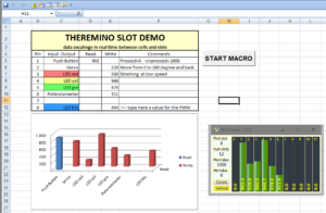
Even without knowing programming languages evolved, you could use an Excel sheet and write macros in VBA (Visual Basic for Applications) to experience times, intensity and programs with reps of each type.
A device controlled by a TaBLET
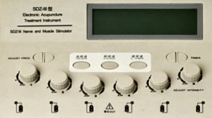
Several times we were asked to design a device like this. And they also prepared an analysis of how commercial appliances are made and how we should design it:
– Microcontroller programmed with a firmware that determines the timing and manages a menu.
– Two-line display connected to I2C to present the menu.
– Buttons to select the menu in the display.
– Knobs for easy adjustments on the menu would be too uncomfortable.
– Batteries so you have a handset and secure (not plugged in).
– Connector for charging the batteries and circuit inside to load them too.
In practice something like you see in this picture (click on the image to see it better).
We thank those who have written for their research work, but the way thereminica is different, it minimizes hardware and l ’ leans to a PC, or rather in this case to a Tablet that will also power the circuits (up to 12 independent).
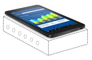 With a Tablet you can use its batteries and remain isolated from the mains supply for safety. You do not have to build circuit boards, LCD display and buttons. And instead of four knobs and a small display has a full color touch screen Panel, the batteries, the charging circuit, the state of charge indicator, l ’ power pack law, the remote connection over WiFi, the audio and speakers…
As well as a variety of memory and computing power. All in little volume, with a few Watts of total consumption and (all counted) also saving.
Cheap Tablets exist from 7 inches with prices from 50 AI 100 Euro but be careful that the operating system must be Windows10.
Wiring diagram
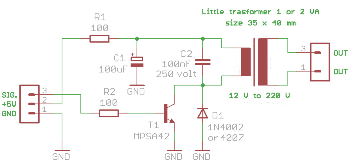
The scheme is simple and achievable with easily available components. Even the transistor, that is a special component from 300 volts, can be retrieved from a fluorescent lamp burned. Read the release notes for the transistor T1.
- The input connector (Ms/+5/GND) connects directly to a Master module Pin configured as Pwm16 that provides both feed the control signal. The Master module in turn will be linked to your Tablet with a USB cable.
- R1 – Limits the current you can draw from 5 volts not more than 50 mA. So even if you missed the pilot, and instead of sending short pulses of a few milliseconds it takes endlessly active, nothing happens untoward, the components do not heat up and the electricity purchased from the USB port is not excessive.
- C1 – Store enough energy for a boost at maximum power. But if you get it wrong and you send impulses too frequent or even continuous signal, its voltage drops and within seconds the supply current is limited to 50 But coming from R1.
- C2 – Limits the voltage on the collector of T1 to no more than 100 volts. If it were not for this capacitor and turning on the device with an electrode, the pulse voltage may rise even over a thousand volts and impair the transistors and the isolation transformer.
- R2 – Limits the piloting current base of transistor in about twenty milliamperes.
- T1 – And’ an NPN transistor for at least 300 volts and at least 500 mA. You could replace with any transistor recovered from fluorescent lamps (those calls to energy savings). Usually in these lamps are the MJE13002 or the STX13003 or the TS13003. But be careful that the PIN layout may not be the same (CBE instead of EBC) and then the body of the transistor should be rotated 180 degrees. The transistor should be recovered from a few Watts lamps might otherwise use the 13007 they are bigger and uncomfortable to be welded. Transistors of energy saving lamps are also best of MPSA42, the maximum output current rises from 12 but until almost 15 mA.
- D1 – Limits the negative voltage to -0.7 volts to protect the transistor T1 if you turn on the unit using the electrodes detached.
- The transformer marked 12 to 220v is a small power transformer from approximately 30 x 40 mm. By accepting a small reduction of the maximum output current (10 but instead of 12) you could also use transformers 9 volts or 24 volts (always with the primary 220 volts). If it were a primary transformer 110 volts you'd get a slight increase of the maximum current which would rise from 12 but about 15.
- The output connector (OUT/OUT) that will signal to the electrodes to be applied on the skin. Between the two poles OUT – OUT you can add a resistor from 22k to limit the maximum output voltage to about 80 volts. See section “Limit the output voltage” towards the end of the article.
Safety
Premise: TENS devices should not be used by anyone who uses a pacemaker and electrodes should never be placed so that the current flow through the heart. They are probably excessive recommendations but it is good to respect them.
This generator is intrinsically safe, the maximum current is 12 but you can't increase it even by mistake. We start from just 5 volts and c ’ is just a resistor from 100 ohm in series that limits supply current to less than 50 mA. Then these 50 but they are divided by the ratio of the transformer and is unable to get more than a few milliamps for a fraction of a millisecond less than change almost all circuit components.
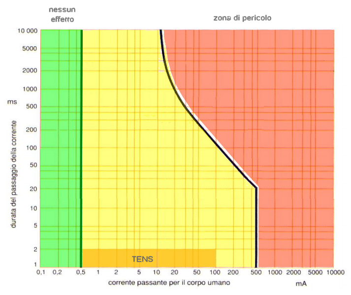
A current of 12 but it could, in some cases, be painful but is considered completely safe. In addition, given that the pulses are short (few milliseconds at maximum), the current that is considered dangerous is much higher, as seen in the next picture.
Looking at this picture, you can see that 12 But even a few. Some commercial devices reaching 50 but and beyond. From the evidence made it seems to us that 12 but are sufficient but we will suggest variants for those wishing to increase the current.
Output current
The output current is adjusted with the PWM signal from zero up to just under 12 mA. The current is quite independent of the body's resistance (in about 500 ohm and 10 000 ohm resistor) and form d ’ output is balanced (equal negative energy in the positive) in order to minimize the risk of skin reactions.
The waveform of the output current is the classic one of TENS devices, that is a positive square-wave lasting a few milliseconds, followed by a negative pulse back to zero so that it has the same asymptotic and positive half-wave area in order to balance the total and avoid galvanic dissociation effects and electrophoresis.
Construction
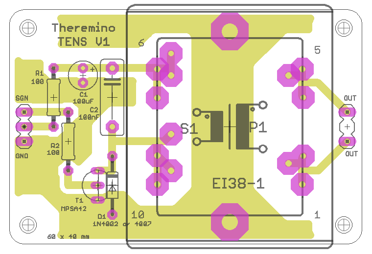
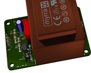
Using this picture, you could also do without the printed circuit board. The components are few so just a piece of stripboard and some bare wire from the same resistors.
The form is smaller than it looks, just 60 x 40 mm (as a Master module). In a large box a notch if they can assist you. In the back of the Master with the USB socket, on the front you are taken to the TENS and cables on the upper side leans on Tablet, Maybe with a little’ velcro to hold it in place. EBay and Amazon you can find spare parts and accessories measuring cables, for example the sponges to moisten with water.
No need for a power supply. You plug the USB cable and the Tablet's battery can supply up to 6 or 12 outputs for many hours. The consumption of two-dozen exits set for maximum repetition and possible current is more or less the same as the display of the Tablet in half light. With six outputs just lower the display brightness to the minimum and you get a range of more than six hours.
The transformer
On the printout, there are several holes for some of the most common transformers. If the holes do not match you can make more holes with the drill and use small wires on the underside for links.
The transformer can be both 220 volts from 110 volts and the secondary can be from 9, 12 or 24 volts, but in all cases you will get a maximum current greater than 12…15 mA. To increase the power it would take a special transformer as explained in the next chapter.
In all cases it is good that the transformer has two windings separated by a plastic divider. If the transformer is constructed with the divider then you get a safe isolation and you could use the device even when it is connected to the power supply that charges the batteries.
Increase the output current
For almost all people a current of 12…15 but is already sufficient and even too much. But someone might want to increase to the levels of the most powerful commercial appliances.
To obtain a maximum current of 50 but it would take a transformer and over 50…100 MH low voltage side and 200…400 MH electrodes output side. In practice, the ratio of turns should be about two and then the relationship between the impedances around four times.
- Use a transformer specially built for TENS.
- Build this transformer with a ferrite core with double “U” and two separate windings, one on one leg and one on the other.
- Try a transformer which has two separate windings, one from 12 volts and one from 24 volts. But in this case you should delete the wrapping that was scheduled for 220 volts in order to avoid that on it to develop too high voltages able to pierce the insulation of its enameled wire.
- Or you could use a transformer with 12 primary v 110 or 220 volts and eliminate from the primary large part of the wire until that its impedance becomes four times that of the winding to 12 volts.
Limit the output voltage
If you use a transformer with 110 or 220 you get almost constant current output volts. This means that if the resistance between the electrodes rises then the voltage also increases and the current remains almost the same. According to some authors, this is desirable because the differences in resistance of the various parts of the body are compensated automatically.
This mode of operation, however, requires that the electrodes are always well moistened and applied correctly. If an electrode did an unstable contact resistance at that point it could rise and the voltage rise also to compensate. In some cases the tension could rise to several hundred volts and you could have very unpleasant sensations at the point of contact or even small Burns.
Why many professional appliances use a cross between constant current and constant voltage and in practice limit the output voltage to about 80 volts, even with the electrodes completely detached and set to maximum output current.
To even get us the operation capped at about 80 volts we have two possibilities:
- Use a separate transformer as explained in the previous chapter “The transformer”. This is the solution used by commercial devices and also allows you to obtain a higher Max current;
- Use transformers 110 or 220 v that are easy to find and add a resistor from 22k (for a quarter of a watt) in parallel to the two poles of exit.
Pilot the circuit with a PWM signal
It starts with a Pwm output of the Master and with a few instructions software you can get all the repetitions that you want from 1 Hz to 100 Hz and beyond. And always through the Pwm signal current can be adjusted from zero up to a painful milliampere current.
Current regulation
By adjusting the Duty Cycle of the Pwm from 0 Ms a 2 mS (from 0 to 500 on Slot) pulse current varies from zero to little more than ten but.
You can also adjust the Pwm beyond 2 Ms and current is still growing but we can no longer reach the maximum repetition rate (250 Hz) because in that case the current is limited by R2 which brings down the supply voltage.
Adjusting the repetition in software
1) You set the Slot for the Pwm Pin number from 0 to 1000 which regulates the desired current.
2) They expect about 3…10 Ms to give time to Master to issue from a few pulses.
3) You set the Slot for the Pwm Pin a zero to stop the Pwm.
4) Expect a time from scratch (repetition 250 Hz) up to one second (repetition 1 Hz)
5) Repeats from the point 1
Project download
Theremino_TENS_V1 project
This is the complete design of the PCB in Eagle format, with diagrams, Assembly plans, simulations ltspice, Gcode for the cutter and 3D images.
Theremino_TENS_V1 (zip file from 2 MByte)


