Simple light sensors
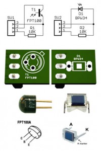
 If using low loss inputs (3, 4, 5 and 6 on the Master – see This section ) You can accurately detect very low amount of light. With the light intensity can be detected by photodiodes BPW34 20 Lux and beyond (resist. of load 50 Kohm; leakage current +/-100nA). With phototransistors FPT100A can be detected intensity until about 1 Lux (resist. of load 50 Kohm; leakage current +/-100nA). To measure the illuminations in a normal working environment it is recommended to use the FPT100 component with resistor from 10 Kohm. If you make an initial calibration and use the difference compared to the set value, You can detect even very small changes in light (invisible to the human eye)
Stairs can be obtained with various combinations of resistors, photo diodes and photo-transistors
Resistor |
Bpw34resolution
|
Bpw34full scale
|
FPT100resolution
|
FPT100full scale
|
50 Kohm |
2 |
20 000 |
0.1 |
1 000 |
10 Kohm |
10 |
100 000 |
0.5 |
5 000 |
1 Kohm |
100 |
1 000 000 |
5 |
50 000 |
500 ohm resistor |
200 |
2 000 000 |
10 |
100 000 |
Lighting reference values
| Sun at noon | 100.000 Lux |
| Tables, operating | 10.000 Lux |
| Office | from 500 Lux a 2.000 Lux |
| Art Gallery | from 100 Lux a 500 Lux |
| Full moon | 1 Lux |
Phototransistors
The FPT100 of the previous paragraph are outdated. Among the recent models, the best for general use are the TEPT4400, TEPT 5600 and TEPT5700. Cheap (less than half a Euro from Mouser) and have a lens that focuses the beam. They are also sensitive to blue light, have an answer very similar to that of the human eye and are very sensitive.
-
The TEPT4440 have a diameter of 3 mm, a bundle of 30 degrees and give about 2 UA for LUX
-
The TEPT5600 have a diameter of 5 mm, a bundle of 20 degrees and give about 3 UA for LUX
-
The TEPT5700 have a diameter of 3 mm, a bundle of 50 degrees and give about 1 UA for LUX
Resolution(Lux) |
Full scale(Lux) |
TEPT4400 (resistor approx) |
Tept5600 (resistor approx) |
TEPT5700
|
0.001 |
10 |
120 Kohm |
100 Kohm |
300 Kohm |
0.01 |
100 |
12 Kohm |
10 Kohm |
30 Kohm |
0.1 |
1 000 |
1.2 Kohm |
1 Kohm |
3 Kohm |
0.5 |
5 000 |
240 ohm resistor |
200 ohm resistor |
600 ohm resistor |
These photo transistors give much current in low light they cannot measure more than 5000 Lux. Better to stick to 1000 Lux, because besides the measures become little linear. Never mind, If you really need to measure strong lights, just add a gray filter or measure the reflected light on a gray area or through a small hole.
These photo transistors can give a current strong enough to exceed the capacity of the input pins (maximum 3.6 Volts and 100 UA). It doesn't break anything but it might happen that, enlightening them strongly, the microcontroller go in error. The result is that locks the USB communication. If this happens add a resistor from 10 at 100 k, in series with the signal wire that goes to the input pins. The thread being aborted is the yellow one (or white) and must be stopped close to the input pins. More info here: technical/communications
Preassembled modules
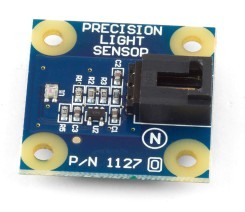
This measurement module 1 Lux (Moonlight) to 1000 Lux (a tv studio lighting)
The output value is easily interpretable thanks to full scale calibrated in lux, so a value of 123.4 you mean, simply, 123.4 Lux. The measured values are stable, accurate and independent of input voltage variations (not ratiometric)
The arrangement of the wires on the connector follows the standard system Theremino:
Signal --- Yellow wire
 +5V ------- Red wire
 GND ------ black or brown wire
–
ATTENTION: If you are powering this module with 5 Volts, When you exceed the 660 Lux the output voltage exceeds the 3.3 Volt acceptable by the input Pin of the system Theremino. To avoid disturbances to the USB communication you must then add a 100 k resistor next to the input pins (cut the yellow wire and put the resistor to no more than a few centimetres from the Master). More info here: technical/communications
This form can be found, for a few euros, at many retailers in Internet. Search “1127 precision-light-sensor”
Here you can download his data sheet:
www.phidgets.com/documentation/Phidgets/1127_0_Product_Manual.pdf
Digital light sensors
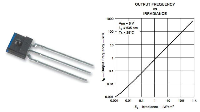
To measure more accurately lighting you must use digital sensors, We recommend the model TSL235R available for a few dollars at robot Italy and other retailers.
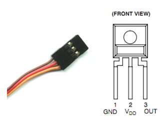
 The supply voltage, from 4.5 to 5.5 volts, and the wiring layout are the same of the connectors of the system Theremino (Gnd-Brown/Red/Yellow Vdd-Out-) why this sensor can be connected directly with the standard cables. To measure low lighting, you can use the pin type “Counter” that is available on all pins. To measure up to the maximum illumination (1k uW/cm2) You must use the pin type “Fast_Counter” on one of the Master Pin 1 to 10. or on pin 8 the slaves “Servant” or on pin 7 the slaves “Generic”.
The count-up timer must then be converted into frequency, by enabling the appropriate box, and time averaged, lowering the value “Speed of response” at a value low enough (usually from 10 to 30). To further stabilise the measured value you may also press the button “Speed of response”.
Photoresistors
The photoresistors come online between mass and signal (the two ends of the connector) allowing the Central wire carrying the power supply. Like Res_8 or Res_16 you choose which type of Pin is available on almost all pins of the slaves. To measure very low lighting, you should choose the photoresistor between models with lower resistance, There are photoresistors enhance measure until a few lux but could use a little large and, Sometimes, expensive. If you were to find a photoresistor with lower resistance to 50 KHM at lower illuminations that are intended to measure then it is better to use the photodiodes, the Phototransistors or previous pages TSL235.


