Comparison of DPM Protocol system Theremino
and the CAN protocol
The CAN is definitely higher than the DPM, as regards the noise immunity, the DPM has a lesser immunity, but a higher repetition rate.
In the presence of strong electrical noise, the DPM can afford to lose a few packs without consequences, due to its high repetition rate.
When there are disturbances (something that normally happens for most of the time), the DPM leverages its high repetition rate (up to over 900 FPS), to allow maximum fluidity, in the control of multimedia systems.
On the following pages, We have gathered important information on the CAN, that could be useful to those wishing to study, an alternative method of communication, for the system Theremino.
Comparing distances and times between DPM and CAN
|
DPM
Speed
|
DPM
time
by cell
|
DPM
bit/s
|
|
Maximum distance
|
|
CAN
bit/s
|
CAN
time
by cell
|
|
1
|
1 mS
|
1K
|
|
10 Km
|
|
|
|
|
2
|
500 uS
|
2K
|
|
5 Km
|
|
|
|
|
3
|
200 uS
|
5K
|
|
2 Km
|
|
|
|
|
4
|
100 uS
|
10K
|
|
1 Km
|
|
62.5K
|
16 uS
|
|
5
|
50 uS
|
20K
|
|
500 m
|
|
125K
|
8 uS
|
|
6
|
20 uS
|
50K
|
|
200 m
|
|
250K
|
4 uS
|
|
7
|
10 uS
|
100K
|
|
100 m
|
|
500K
|
2 uS
|
|
8
|
5 uS
|
200K
|
|
50 m
|
|
600K
|
1.66_ uS
|
|
9
|
2 uS
|
500K
|
|
20 m
|
|
660K
|
1.5 uS
|
|
10
|
1 uS
|
1M
|
|
10 m
|
|
1M
|
1 uS
|
|
11
|
500 NS
|
2M
|
|
5 m
|
|
|
|
|
12
|
250_nS
|
4M
|
|
2.5 m
|
|
|
|
Example with 8 Cap Sensors
– DPM: (24 bit command + 24 data bits) * 8 slaves = 216 bit count
– CAN: (133 bit transmission + 133 bit reception) * 8 slaves = 2128 bit count
In this example, CAN use many more bits, to convey the same information (the ratio of bits is about 10 times)
Note also, the DPM always answers a confirmation, at the end of each command, While the CAN, to give the same security, must send as confirmation, an entire package of response from 133 bytes. In some cases, the ratio of the transmitted bits, exceeds the 20 times.
Packages CAN “Standard” and “Extended”

Figures 2. CAN Standard: 11-Bit Identifier
( 1 + 11 + 1 + 1 + 1 + 4 + 64 + 16 + 2 + 7 + 7 = 64 + 51 = 115 bits )

Figures 3. Extended CAN: 29-Bit Identifier
(1 + 11 + 1 + 1 + 16 + 1 + 1 + 1 + 4 + 64 + 16 + 2 + 7 + 7 = 64 + 69 = 133 bits)
The CAN communication protocol is a carrier-sense multiple access protocol with collision detection and arbitration-on message priority (CSMA/CD + AMP). CSMA means that each node on a bus must wait for a prescribed period of inactivity before attempting to send a message.
CD+AMP means that collisions are resolved through a bit-wise arbitration, based upon a preprogrammed priority of each message in the identifier field of a message. The higher priority identifier always wins bus access.
The first version of the CAN standards listed in Table 1, ISO 11519 (Low-Speed CAN) is for applications up to 125 kbps with a standard 11-bit identifier. The second version, ISO 11898 (1993), also with 11-bit identifiers provides for signaling rates from 125 kbps to 1 Mbps while the more recent ISO 11898 amendment (1995) introduces the extended 29-bit identifier. The ISO 11898 11-bit version is often referred to as Standard CAN Version 2.0A, while the ISO 11898 amendment is referred to as Extended CAN Version 2.0B.
The Standard CAN 11-bit identifier field in Figure 2 provides for 211, or 2048 different message identifiers, while the Extended CAN 29-bit identifier in Figure 3 provides for 229, or 537 million identifiers.
Il cavo di trasmissione
The cable is specified to be a shielded or unshielded twisted-pair with a 120-O characteristic impedance (Zo). The standard defines the interconnection to be a single twisted-pair cable.
The interconnection is terminated at both ends with a resistor equal to the characteristic impedance of the line to prevent signal reflections. Nodes are then connected to the bus with unterminated drop cables, or stubs, which should be kept as short as possible to minimize signal reflections.
If multiple devices are placed along the cable, only the devices on the ends of the cable need termination resistors. Figures 2 shows an example of how to terminate a high-speed network.

Figures 2 – Terminating a High-Speed Network
Note per l’utilizzo con il sistema Theremino
– Il cavo CAN deve essere twistato.
– Con i cavetti standard non è possibile portare CAN e alimentazione a 5 volts
Una buona soluzione, potrebbero essere 2 doppini twistati, con connettori RJ da 4 poli. (più o meno come un cavo di rete a 4 wires)
Anche se il cavo non deve essere passante, sarebbero ugualmente necessari due connettori per ogni slave.
Note sulla lunghezza dei collegamenti CAN
CAN Rates are achieved with the SN65HVD230 in high-speed mode (Texas Instruments 2003) The ISO 11898 standard specifications are given for a maximum bus length of 40 m and maximum stub length of 0.3 m with a maximum of 30 nodes. However, with careful design, longer cables, longer stub lengths, and many more nodes can be added to a bus — always with a trade-off in signaling rate. A transceiver with high input impedance such as the HVD230 is needed to increase the number of nodes on a bus.
The CAN requires an external transceiver
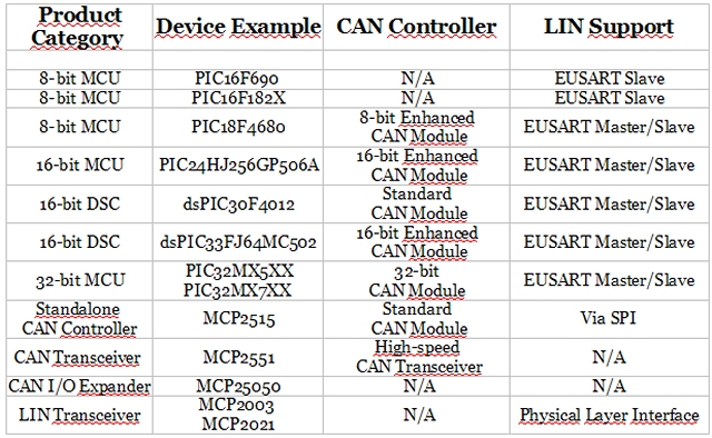
PIC – Can/LIN Products
(by Microchip Connectivity – Summer 2010)
The microcontroller doesn't have the CAN transceiver. You must add it externally, as in the CAN controllers shown above.
CAN – Noise immunity
The CAN bus has excellent High Short-Circuit Protection, High ESD Protection, Wide Common-Mode Range, Common-Mode Rejection and has a high noise immunity, in harsh environments.
These features indicate that the CAN makes few mistakes and does not break, but that doesn't mean I don't make mistakes, in the presence of disorders.
Error Checking and Fault Confinement
The CAN protocol incorporates five methods of error checking: three at the message level and two at the bit level. If a message fails with any one of these error detection methods, it is not accepted and an error frame is generated from the receiving nodes, causing the transmitting node to resend the message until it is received correctly. However, if a faulty node hangs up a bus by continuously repeating an error, its transmit capability is removed by its controller after an error limit is reached.
At the message level are the CRC and the ACK slots displayed in Figures 2 and 3. The 16-bit CRC contains the checksum of the preceding application data for error detection with a 15-bit checksum and 1-bit delimiter. The ACK field is two bits long and consists of the acknowledge bit and an acknowledge delimiter bit. Finally, at the message level there is a form check. This check looks for fields in the message which must always be recessive bits. If a dominant bit is detected, an error is generated. The bits checked are the SOF, EOF, ACK delimiter, and the CRC delimiter bits.
At the bit level each bit transmitted is monitored by the transmitter of the message. If a data bit (not arbitration bit) is written onto the bus and its opposite is read, an error is generated. The only exceptions to this are with the message identifier field which is used for arbitration, and the acknowledge slot which requires a recessive bit to be overwritten by a dominant bit. The final method of error detection is with the bit stuffing rule where after five consecutive bits of the same logic level, if the next bit is not a compliment, an error is generated. Stuffing ensures rising edges available for on-going synchronization of the network, and that a stream of recessive bits are not mistaken for an error frame, or the seven-bit interframe space that signifies the end of a message. Stuffed bits are removed by a receiving node’s controller before the data is forwarded to the application.
With this logic, an active error frame consists of six dominant bits—violating the bit stuffing rule. This is interpreted as an error by all of the CAN nodes which then generate their own error frame. This means that an error frame can be from the original six bits to twelve bits long with all the replies. This error frame is then followed by a delimiter field of eight recessive bits and a bus idle period before the corrupted message is retransmitted. It is important to note that the retransmitted message still has to contend for arbitration on the bus.
CAN – The layered ISO 11898
The CAN bus was developed by BOSCH as a multi-master, message broadcast system that specifies a maximum signaling rate of 1M bit per second (bps).
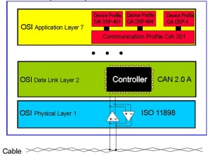
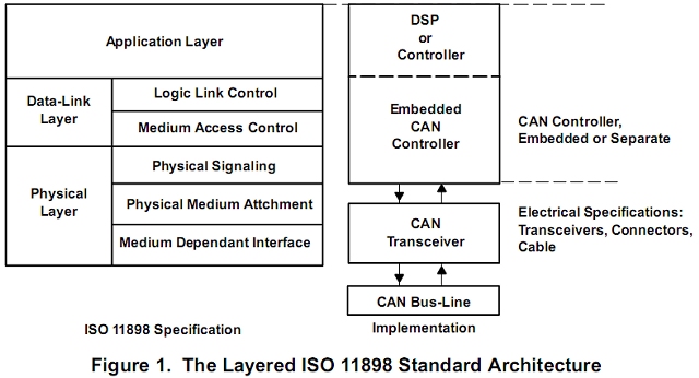
The CAN communications protocol, ISO 11898, describes how information is passed between devices on a network, and conforms to the Open Systems Interconnection (OSI) model that is defined in terms of layers. Actual communication between devices connected by the physical medium is defined by the physical layer of the model. The ISO 11898 architecture defines the lowest two layers of the seven layer OSI/ISO model as the data-link layer and physical layer in Figure 1.


